4OM-1011-002.pdf - 第200页
0305-001 Tg0860-PM-MM 7.2 COMPONENT RECOG. TEST Display 3-149 7.2.6 Result of Component Recognition • After recognition is completed normally for component recognition test, the following (example) appears on the recogni…
0305-001 Tg0860-PM-MM
7.2.5 COMPONENT RECOG. TEST - TRAY COMPONENT
SUPPLY/STORAGE Display (Option)
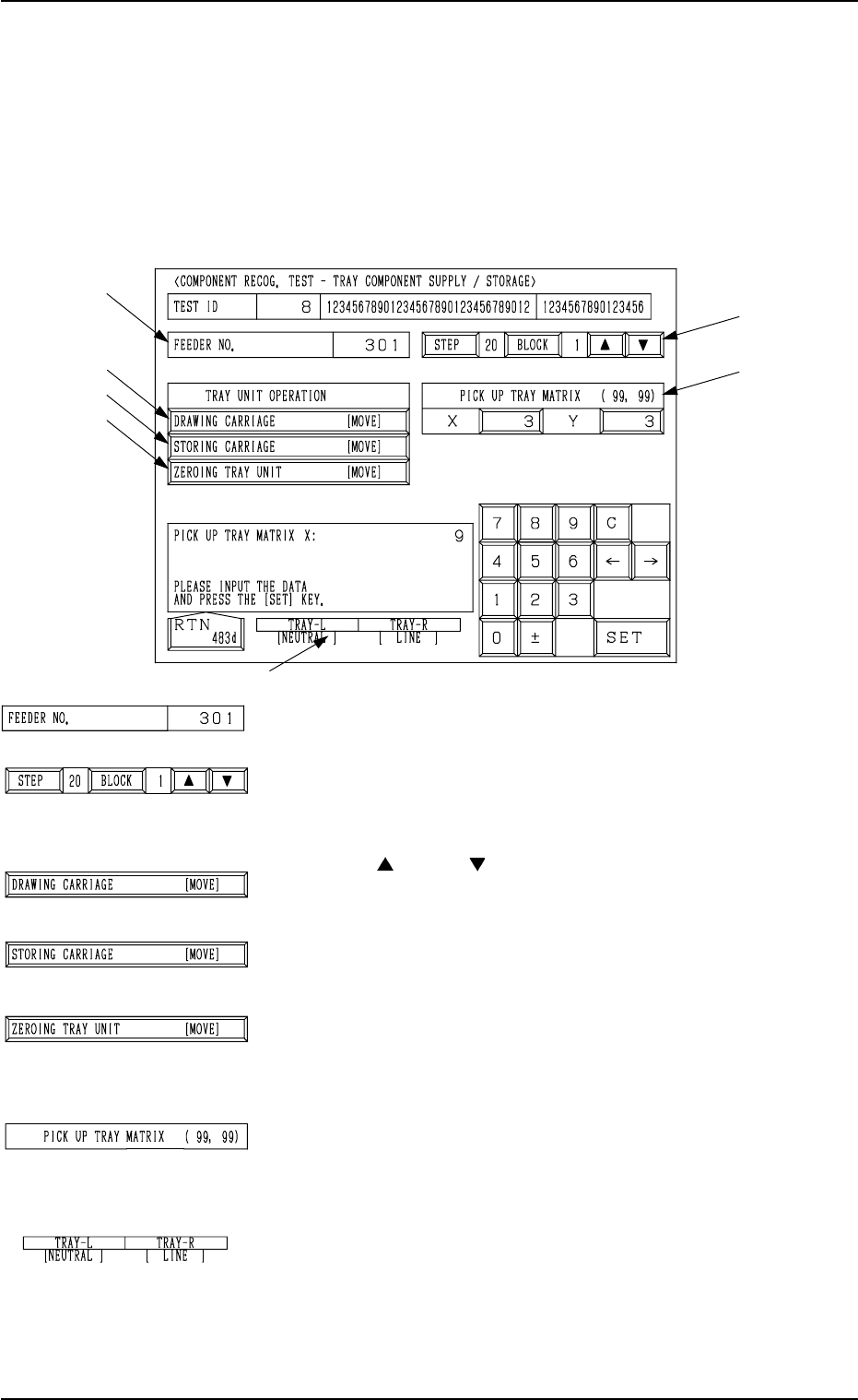
• This display allows the operator to draw out and store the tray components
(pallet) and change the tray pick-up matrix when the component recognition
test is made on the tray components.
When the [TRAY COMP. SET-UP/COLLECT] key is pressed at the “COM-
PONENT RECOG. TEST” display, the following display appears on the screen.
*1 “FEEDER NO.”
Displayed is the feeder No. which was set at the display
(Fig. 4C290).
*2 [STEP] and [BLOCK] Keys
Displayed are the step and block numbers which were set
at the display (Fig. 4C290).
When there are several steps and blocks, set the numbers
with the [ ] or the [ ] key.
*3 [DRAWING CARRIAGE [MOVE]] Key
When this key is selected and the [MOVE] button is pressed,
the pallet selected in *1 and *2 is drawn out.
*4 [STORING CARRIAGE [MOVE]] Key
When this key is selected and the [MOVE] button is pressed,
the drawn pallet is stored.
*5 [ZEROING TRAY UNIT [MOVE]] Key
This key is used to zero the multi-layer tray feeder
(option).
When this key is selected and the [MOVE] button is pressed,
the zeroing operation starts.
*6 “PICK UP TRAY MATRIX (99, 99)”
The matrix for the subsequent component pick can be speci-
fied.
The numerical values in parentheses show the maximum
ones for the selected tray (block).
*7 “TRAY-L” and “TRAY-R”
It is shown which mode “[NEUTRAL], [LINE], or [LO-
CAL]” the right and left multi-layer tray feeders are in and
whether they are zeroed or not.
When the multi-layer tray feeder is zeroed, “” appears.
Note: The condition of the disconnected multi-layer tray
feeder is not shown.
7.2 COMPONENT RECOG. TEST Display
3-148
*2
*6
*1
*3
*4
*5
*7
Fig. 4C308
Fig. 4C309
Fig. 4C310
Fig. 4C311
Fig. 4C312
Fig. 4C313
Fig. 4C314
Fig. 4C315
0305-001 Tg0860-PM-MM
7.2 COMPONENT RECOG. TEST Display
3-149
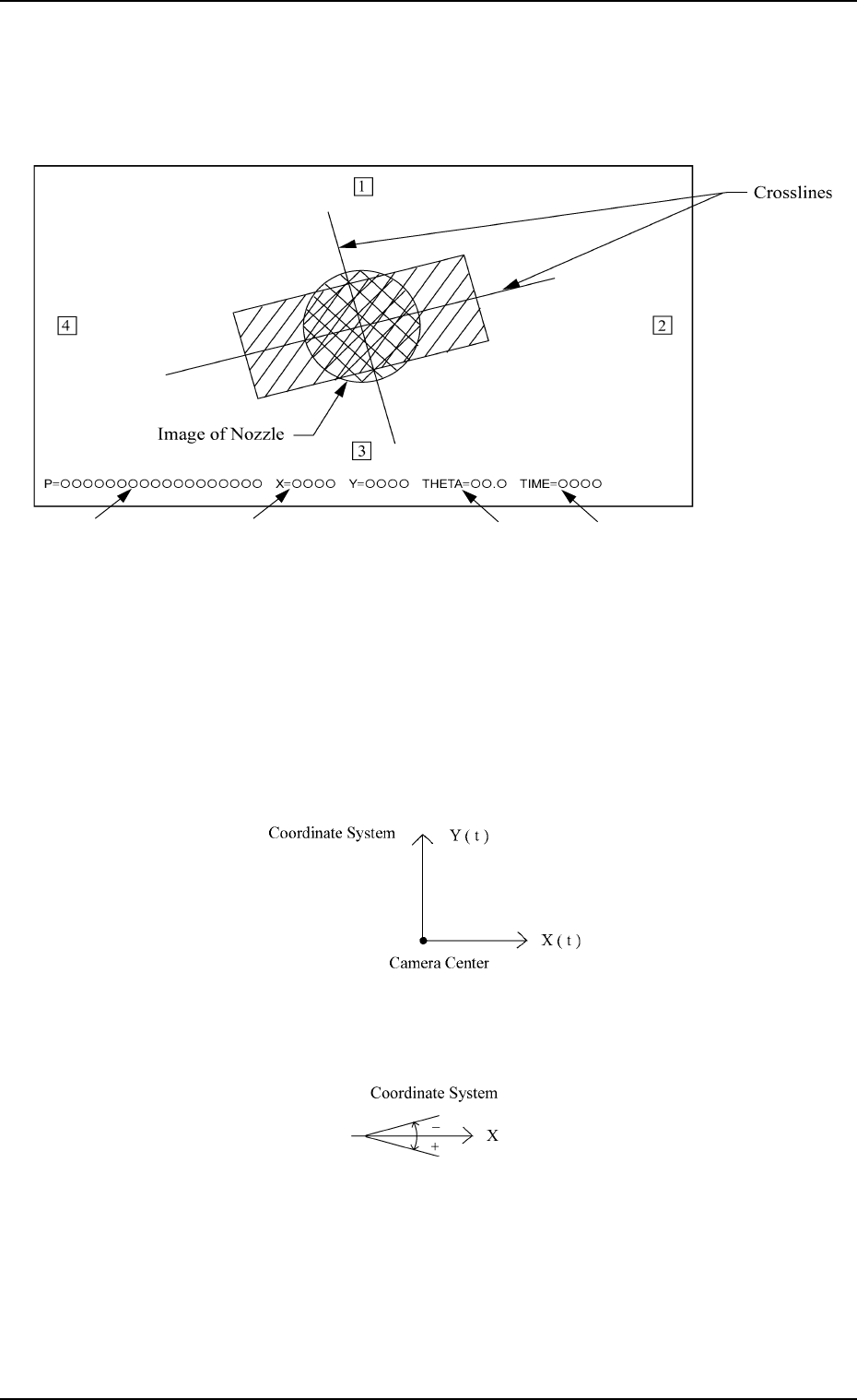
7.2.6 Result of Component Recognition
• After recognition is completed normally for component recognition test, the
following (example) appears on the recognition monitor.
*1 P
= =
= =
=
{{{{{{{{{{{{{{{{{{
This shows a component ID name for component recognition test.
*2 X
= =
= =
=
{{{{, Y
= =
= =
=
{{{{(Unit:µm)
These show positional deviation (X and Y) of the component to be picked
up from the camera center. The point of intersection of the crosslines shows
the center of positioned component.
The outline and graphic of the component and the directions (1, 2, 3, and 4)
in the library data are also shown at the same time.
Note: The point of intersection of the crosslines is the place where a com-
ponent must be positioned.
*3 THETA
= =
= =
=
{{.{(Unit: Degree)
This shows angular deviation (inclination of crosslines) of the picked com-
ponent.
*4 TIME = {{{{(Unit: 1/1000 seconds)
This shows the processing time of component recognition.
Use the value as a reference to be set in the “RECOG. TIME” data box at
the “COMPONENT LIBRARY” display.
• When an error in recognition occurs during component recognition test, an
error message (a recognition error) is issued on the touch screen.
*1 *2
*3
*4
Fig. 4C316
Fig. 4C317
Fig. 4C318

0305-001 Tg0860-PM-MM
7.2 COMPONENT RECOG. TEST Display
3-150
7.2.7 Procedure for Component Recognition Test
The following three operations are available in component recognition tests.
• To attach a component manually and perform a test
• To draw out a pallet manually, pick up a component automatically from the
tray, and perform a test
• To pick up components automatically from each feeder (tape and vibratory
stick feeders) and perform a test
Each operation procedure is shown below.
To attach a component manually and perform a component
recognition test
(1) Press the [SET TEST ID] key at the display (Fig. 4C265). The “SET
TEST ID” display appears on the screen.
Register the component ID to be tested as a test ID.
Refer to “7.2.1 SET TEST ID Display of Section 3” for details.
(2) Check “NOZZLE TYPE” at the display (Fig. 4C265) and press the
[MANUAL NOZZLE CHANGE OPE] key. The “MANUAL NOZZLE
CHANGE OPERATION” display appears on the screen.
Attach the nozzle specified for “NOZZLE TYPE”.
When the pertinent nozzle is not found, open the “NOZZLE TYPE DATA”
and “NOZZLE DATA” displays and register parameters. Then, attach the
nozzle. (Hierarchical Sequence: “DATA EDIT” Display → “NOZZLE
TYPE DATA” Display or “NOZZLE DATA” Display)
(3) Press the [SET FEEDER] key at the display (Fig. 4C265). The “SET
FEEDER” display appears on the screen.
Set the feeder No. so that the installed feeder is not located at the position
where it does not get in the way of manual component attachment.
Select the [FDR-A CTR.] key when the manual component attachment is
performed on the beam A side or the [FDR-B CTR.] key when the attach-
ment is made on the beam B side.
Refer to “7.2.2 COMP. RECOG. TEST - SET FEEDER Display of Sec-
tion 3” for details.
(4) Select the head where the nozzle on the operation side is attached, using
the related keys in the “SELECT HEAD/CAMERA” group box.
(5) Select the camera to be used to capture an image, using the related keys in
the “SELECT HEAD/CAMERA” group box.
(6) Set “ENABLE” in the “CARRIER MODE” data box.
(7) Set “OFF” in the “VACUUM VALVE” data box.
(The vacuum valve turns ON automatically.)
(8) Select the [PICK FROM FEEDER (MANUAL) [MOVE]] key and press
the [MOVE] button.
The head moves to the position of the specified feeder No. and the vacuum
valve turns ON automatically.
(9) Set the [OPERATION/SET UP] switch to the “SET UP” side.
(10) Press the [READY] button. The LED extinguishes.
(11) Open the supply cover and manually attach the component to the center
of the nozzle.
(12) Press the [READY] button. The LED illuminates.
(13) Set the [OPERATION/SET UP] switch to the “OPERATION” side.