4OM-1011-002.pdf - 第204页
0305-001 Tg0860-PM-MM 7.2 COMPONENT RECOG. TEST Display 3-153 T o draw out a pallet manually , pick up a component automatically from the tray , and perform a component recognition test (1 ) Press the [SET TEST ID] key a…
0305-001 Tg0860-PM-MM
7.2 COMPONENT RECOG. TEST Display
3-152
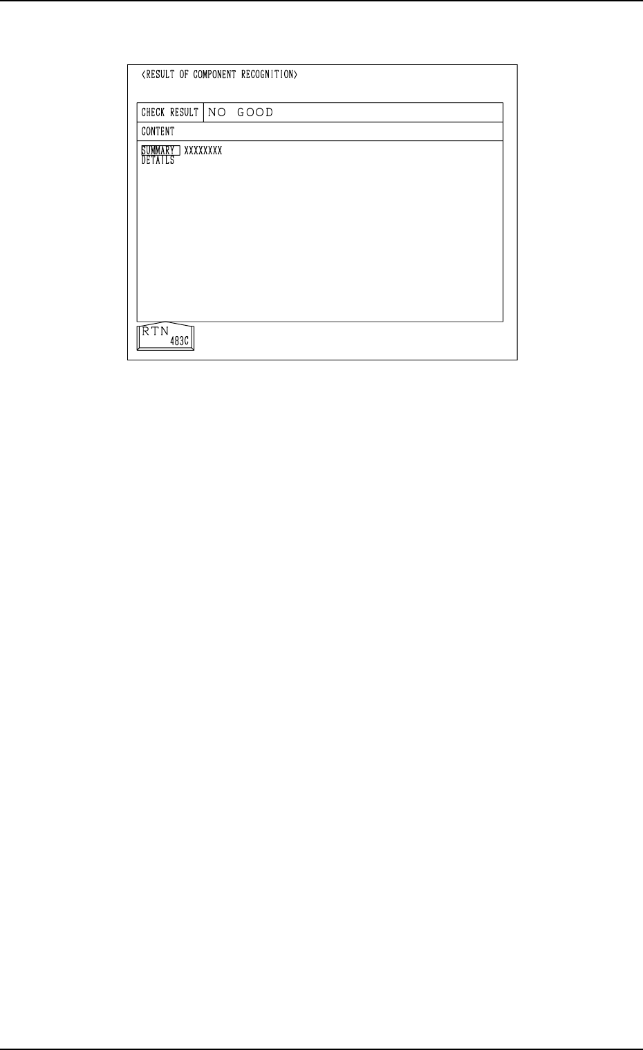
Case: An error was found in the recognition.
(16) Press the [COMP. RECOG. (MANUAL)] key. The “COMP. RECOG.
(MANUAL)” display appears on the screen.
• When the result of the recognition is “OK”, proceed to Step (18).
• When the result of the recognition is “NG (No Good)”, proceed to Step
(17).
(17) Use the “CAMERA”, “CORRECT PICKED POSITION [MOVE]”, and
“RECOGNITION LIGHTING SET” menus at the “COMP. RECOG.
(MANUAL)” display and re-perform the component recognition test.
(18) Perform a hysteresis test at the “HYSTERESIS TEST” display.
Refer to “7.2.4 HYSTERESIS TEST Display of Section 3” for details.
(19) Select the [COMP. COLLECTION [MOVE]] key and press the [MOVE]
button.
Components are collected (discharged) and the X/Y beam is zeroed.
The components are discharged to the component discharge box near the
X/Y beam or the component discharge conveyor (option).
To collect a component by hand, select the [PICK FROM FEEDER
(MANUAL) [MOVE]] key to move the component to the pick-up posi-
tion and collect it there.
After that, press the [COMP. COLLECTION [MOVE]] key to implement
the component collection operation and then zero the X/Y beam.
Note: The display cannot be resumed when the vacuum valve is kept
“ON” (a component is picked up).
Abnormal Completion of Recognition
Fig. 4C321

0305-001 Tg0860-PM-MM
7.2 COMPONENT RECOG. TEST Display
3-153
To draw out a pallet manually, pick up a component automatically
from the tray, and perform a component recognition test
(1) Press the [SET TEST ID] key at the display (Fig. 4C265). The “SET
TEST ID” display appears on the screen.
Register the component ID to be tested as a test ID.
Refer to “7.2.1 SET TEST ID Display of Section 3” for details.
(2) Check “NOZZLE TYPE” at the display (Fig. 4C265) and press the
[MANUAL NOZZLE CHANGE OPE] key. The “MANUAL NOZZLE
CHANGE OPERATION” display appears on the screen.
Attach the nozzle specified for “NOZZLE TYPE”.
When the pertinent nozzle is not found, open the “NOZZLE TYPE DATA”
and “NOZZLE DATA” displays and register parameters. Then, attach the
nozzle. (Hierarchical Sequence: “DATA EDIT” Display → “NOZZLE
TYPE DATA” Display or “NOZZLE DATA” Display).
(3) Open the “COMPONENT REPLENISHMENT” display for the multi-
layer tray feeder (option) and check whether or not any component short-
age error has occurred in the steps for the production model.
If a component shortage error has occurred in a step, replenish the step
with components.
Refer to the instruction manual of the multi-layer tray feeders for details.
(4) Press the [SET FEEDER] key at the display (Fig. 4C265). The “SET
FEEDER” display appears on the screen.
Use the “CURRENT PRGM. (COMP. DATA) REF.” function to select
the [TRAY-L 301-] or the [TRAY-R 601-] key to specify the same com-
ponent ID (feeder No.) as the set test ID.
Refer to “7.2.2 COMP. RECOG. TEST - SET FEEDER Display of Sec-
tion 3” for details.
(5) Select the head where the nozzle on the operation side is attached, using
the related keys in the “SELECT HEAD/CAMERA” group box.
(6) Select the camera to be used to capture an image, using the related keys in
the “SELECT HEAD/CAMERA” group box.
(7) Set “OFF” in the “VACUUM VALVE” data box.
(The vacuum valve turns ON automatically.)
(8) Open the “COMPONENT RECOG. TEST - TRAY COMPONENT SUP-
PLY/STORAGE” display. Select the [DRAWING CARRIAGE [MOVE]]
key and press the [MOVE] button.
The pallet is drawn out.
(9) Select the [PICK FROM FEEDER (AUTO) [MOVE]] key and press the
[MOVE] button.
A component is picked up from the tray which was drawn out.
(10) Select the [MOVE TO RECOG. STATION & RECOG. [MOVE]] key
and press the [MOVE] button.
The component recognition test is implemented.
(11) To manually attach the component, refer to Steps (15) through (19).
(12) Select the [STORING CARRIAGE [MOVE]] key and press the [MOVE]
button.
The tray that was drawn out is stored back in the magazine.

0305-001 Tg0860-PM-MM
7.2 COMPONENT RECOG. TEST Display
3-154
To pick up components automatically from each feeder (tape
andvibratory stick feeders) and perform a component recognition test
(1) Press the [SET TEST ID] key at the display (Fig. 4C265). The “SET
TEST ID” display appears on the screen.
Register the component ID to be tested as a test ID.
Refer to “7.2.1 SET TEST ID Display of Section 3” for details.
(2) Check “NOZZLE TYPE” at the display (Fig. 4C265) and press the
[MANUAL NOZZLE CHANGE OPE] key. The “MANUAL NOZZLE
CHANGE OPERATION” display appears on the screen.
Attach the nozzle specified for “NOZZLE TYPE”.
When the pertinent nozzle is not found, open the “NOZZLE TYPE DATA”
and “NOZZLE DATA” displays and register parameters. Then, attach the
nozzle. (Hierarchical Sequence: “DATA EDIT” Display → “NOZZLE
TYPE DATA” Display or “NOZZLE DATA” Display).
(3) Replenish the feeders for the production model with components.
Refer to the instruction manual of the tape and vibratory stick feeders for
details.
(4) Press the [SET FEEDER] key at the display (Fig. 4C265). The “SET
FEEDER” display appears on the screen.
Use the “CURRENT PRGM. (COMP. DATA) REF.”function to select
the [FDR. - A 101-] or the [FDR. - B 201-] key to specify the same com-
ponent ID (feeder No.) as the set test ID.
Refer to “7.2.2 COMP. RECOG. TEST - SET FEEDER Display of Sec-
tion 3” for details.
(5) Select the head where the nozzle on the operation side is attached, using
the related keys in the “SELECT HEAD/CAMERA” group box.
(6) Select the camera to be used to capture an image, using the related keys in
the “SELECT HEAD/CAMERA” group box.
(7) Set “ENABLE” in the “CARRIER MODE” data box.
(8) Set “OFF” in the “VACUUM VALVE” data box.
(The vacuum valve turns ON automatically.)
(9) Select the [PICK FROM FEEDER (AUTO) [MOVE]] key and press the
[MOVE] button.
The head moves to the position of the specified feeder No. and picks up
the component.
(10) Select the [MOVE TO RECOG. STATION & RECOG. [MOVE]] key
and press the [MOVE] button.
The component recognition test is implemented.
(11) To manually attach the component, refer to Steps (15) through (19).