4OM-1011-002.pdf - 第205页
0305-001 Tg0860-PM-MM 7.2 COMPONENT RECOG. TEST Display 3-154 T o pick up components automatically from each feeder (tape andvibratory stick feeders) and perform a component recognition test (1 ) Press the [SET TEST ID] …

0305-001 Tg0860-PM-MM
7.2 COMPONENT RECOG. TEST Display
3-153
To draw out a pallet manually, pick up a component automatically
from the tray, and perform a component recognition test
(1) Press the [SET TEST ID] key at the display (Fig. 4C265). The “SET
TEST ID” display appears on the screen.
Register the component ID to be tested as a test ID.
Refer to “7.2.1 SET TEST ID Display of Section 3” for details.
(2) Check “NOZZLE TYPE” at the display (Fig. 4C265) and press the
[MANUAL NOZZLE CHANGE OPE] key. The “MANUAL NOZZLE
CHANGE OPERATION” display appears on the screen.
Attach the nozzle specified for “NOZZLE TYPE”.
When the pertinent nozzle is not found, open the “NOZZLE TYPE DATA”
and “NOZZLE DATA” displays and register parameters. Then, attach the
nozzle. (Hierarchical Sequence: “DATA EDIT” Display → “NOZZLE
TYPE DATA” Display or “NOZZLE DATA” Display).
(3) Open the “COMPONENT REPLENISHMENT” display for the multi-
layer tray feeder (option) and check whether or not any component short-
age error has occurred in the steps for the production model.
If a component shortage error has occurred in a step, replenish the step
with components.
Refer to the instruction manual of the multi-layer tray feeders for details.
(4) Press the [SET FEEDER] key at the display (Fig. 4C265). The “SET
FEEDER” display appears on the screen.
Use the “CURRENT PRGM. (COMP. DATA) REF.” function to select
the [TRAY-L 301-] or the [TRAY-R 601-] key to specify the same com-
ponent ID (feeder No.) as the set test ID.
Refer to “7.2.2 COMP. RECOG. TEST - SET FEEDER Display of Sec-
tion 3” for details.
(5) Select the head where the nozzle on the operation side is attached, using
the related keys in the “SELECT HEAD/CAMERA” group box.
(6) Select the camera to be used to capture an image, using the related keys in
the “SELECT HEAD/CAMERA” group box.
(7) Set “OFF” in the “VACUUM VALVE” data box.
(The vacuum valve turns ON automatically.)
(8) Open the “COMPONENT RECOG. TEST - TRAY COMPONENT SUP-
PLY/STORAGE” display. Select the [DRAWING CARRIAGE [MOVE]]
key and press the [MOVE] button.
The pallet is drawn out.
(9) Select the [PICK FROM FEEDER (AUTO) [MOVE]] key and press the
[MOVE] button.
A component is picked up from the tray which was drawn out.
(10) Select the [MOVE TO RECOG. STATION & RECOG. [MOVE]] key
and press the [MOVE] button.
The component recognition test is implemented.
(11) To manually attach the component, refer to Steps (15) through (19).
(12) Select the [STORING CARRIAGE [MOVE]] key and press the [MOVE]
button.
The tray that was drawn out is stored back in the magazine.

0305-001 Tg0860-PM-MM
7.2 COMPONENT RECOG. TEST Display
3-154
To pick up components automatically from each feeder (tape
andvibratory stick feeders) and perform a component recognition test
(1) Press the [SET TEST ID] key at the display (Fig. 4C265). The “SET
TEST ID” display appears on the screen.
Register the component ID to be tested as a test ID.
Refer to “7.2.1 SET TEST ID Display of Section 3” for details.
(2) Check “NOZZLE TYPE” at the display (Fig. 4C265) and press the
[MANUAL NOZZLE CHANGE OPE] key. The “MANUAL NOZZLE
CHANGE OPERATION” display appears on the screen.
Attach the nozzle specified for “NOZZLE TYPE”.
When the pertinent nozzle is not found, open the “NOZZLE TYPE DATA”
and “NOZZLE DATA” displays and register parameters. Then, attach the
nozzle. (Hierarchical Sequence: “DATA EDIT” Display → “NOZZLE
TYPE DATA” Display or “NOZZLE DATA” Display).
(3) Replenish the feeders for the production model with components.
Refer to the instruction manual of the tape and vibratory stick feeders for
details.
(4) Press the [SET FEEDER] key at the display (Fig. 4C265). The “SET
FEEDER” display appears on the screen.
Use the “CURRENT PRGM. (COMP. DATA) REF.”function to select
the [FDR. - A 101-] or the [FDR. - B 201-] key to specify the same com-
ponent ID (feeder No.) as the set test ID.
Refer to “7.2.2 COMP. RECOG. TEST - SET FEEDER Display of Sec-
tion 3” for details.
(5) Select the head where the nozzle on the operation side is attached, using
the related keys in the “SELECT HEAD/CAMERA” group box.
(6) Select the camera to be used to capture an image, using the related keys in
the “SELECT HEAD/CAMERA” group box.
(7) Set “ENABLE” in the “CARRIER MODE” data box.
(8) Set “OFF” in the “VACUUM VALVE” data box.
(The vacuum valve turns ON automatically.)
(9) Select the [PICK FROM FEEDER (AUTO) [MOVE]] key and press the
[MOVE] button.
The head moves to the position of the specified feeder No. and picks up
the component.
(10) Select the [MOVE TO RECOG. STATION & RECOG. [MOVE]] key
and press the [MOVE] button.
The component recognition test is implemented.
(11) To manually attach the component, refer to Steps (15) through (19).
0305-001 Tg0860-PM-MM
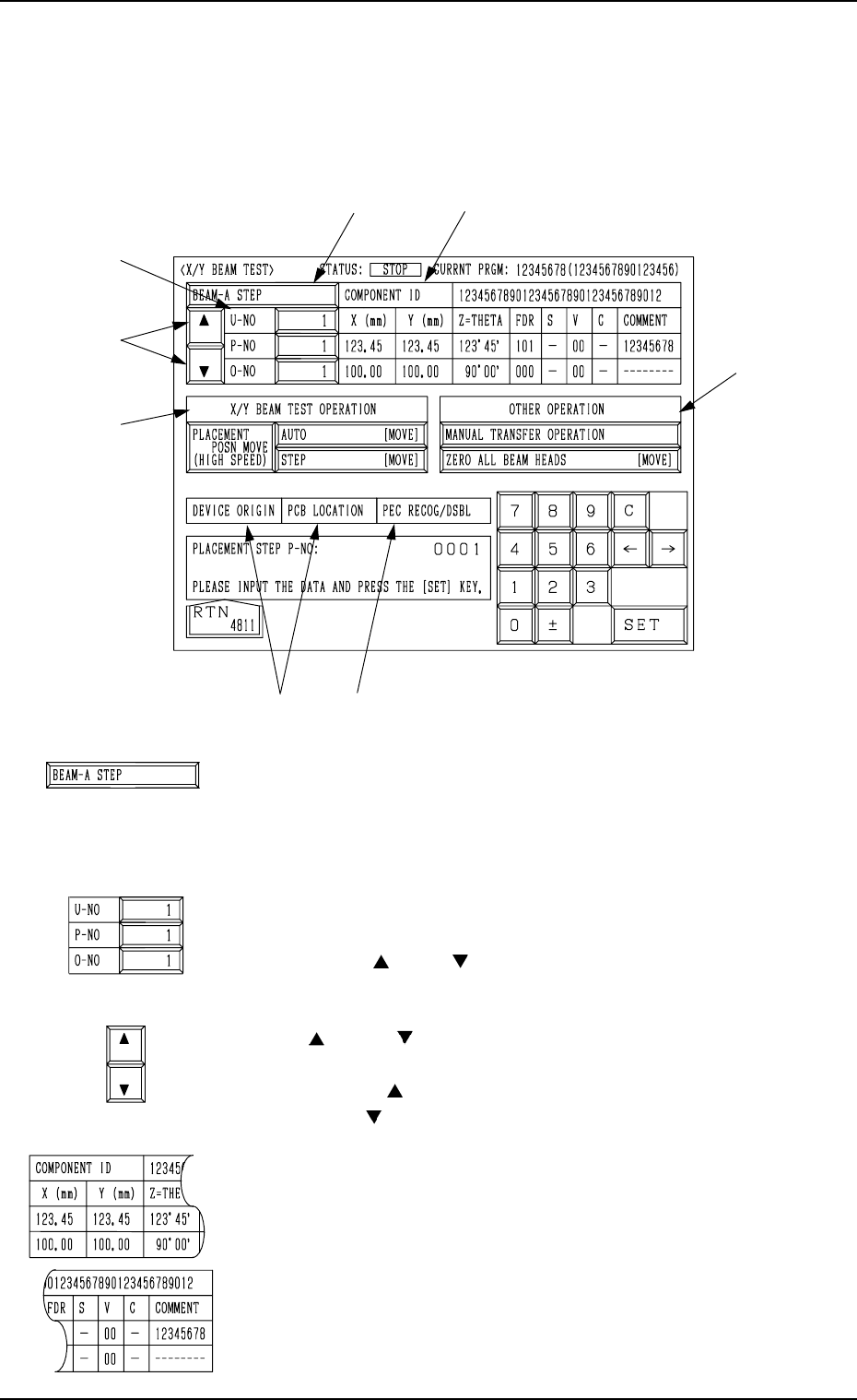
7.3 X/Y BEAM TEST Display
When the [X/Y BEAM TEST] key is pressed at the “DEVICE TEST” display,
the following display appears on the screen.
*1 [BEAM-A STEP] and [BEAM-B STEP] Keys
The X/Y beam to be tested can be selected.
Every time this key is pressed, the label “BEAM-A STEP”
changes to “BEAM-B STEP” or vice versa.
*2 “U-NO”, “P-NO”, and “O-NO”
Shown are the step Nos. of the placement data.
Use the [ ] and [ ] keys to perform the X/Y beam test,
starting with the desired step.
*3 [ ] and [ ] Keys
Select one of the numeric keys *2 and change the step No.
When the [ ] key is pressed, the step No. increases. Press-
ing the [ ] key decreases the step No.
*4 COMPONENT ID/PLACEMENT DATA
Displayed are the parameters of the placement data selected
as those to be tested through program change operation.
7.3 X/Y BEAM TEST Display
3-155
*2
*3
*5
*6
*1
*7
*4
*8
Fig. 4C322
Fig. 4C323
Fig. 4C324
Fig. 4C325
Fig. 4C326