4OM-1011-002.pdf - 第209页
0305-001 Tg0860-PM-MM 8. DEVICE CHECK Display 3-158 8. DEVICE CHECK Display When the [DEVICE CHECK] key is pressed at the “SPECIAL SEL.” display , the following display appears on the screen. [INPUT CHECK] Key When thi…

0305-001 Tg0860-PM-MM
7.3 X/Y BEAM TEST Display
3-157
Procedure for X/Y Beam Test
(1) Set the current pattern program to be tested.
Refer to “5.2 Program Change Operation of Section 2 in Volume 1” for
details.
(2) Confirm that the background color of “DEVICE ORIGIN” and “PEC
RECOG/DSBL” is green.
(3) Select the beam to be tested.
(4) Specify the starting step if desired.
(5) Set the period of time during which the X/Y beam stays still at the place-
ment point.
(6) Specify how to move the X/Y beam.
[AUTO [MOVE]] Key:
The X/Y beam moves continuously according to the pattern program.
[STEP [MOVE]] Key:
The X/Y beam moves step by step according to the pattern program.
(7) The X/Y beam test starts.
Selection of [AUTO [MOVE]] Key
• When the [MOVE] button is pressed, the X/Y beam test run is imple-
mented continuously according to the pattern program.
• When the [STOP] button is pressed during test run, the X/Y beam
completes the movement up to the last step of the pattern program, is
zeroed, and then stops there.
• When the [PAUSE] button is pressed during test run, the X/Y beam
stops temporarily.
Selection of [STEP [MOVE]] Key
• Every time the [MOVE] button is pressed, the X/Y beam moves step
by step.
0305-001 Tg0860-PM-MM
8. DEVICE CHECK Display
3-158
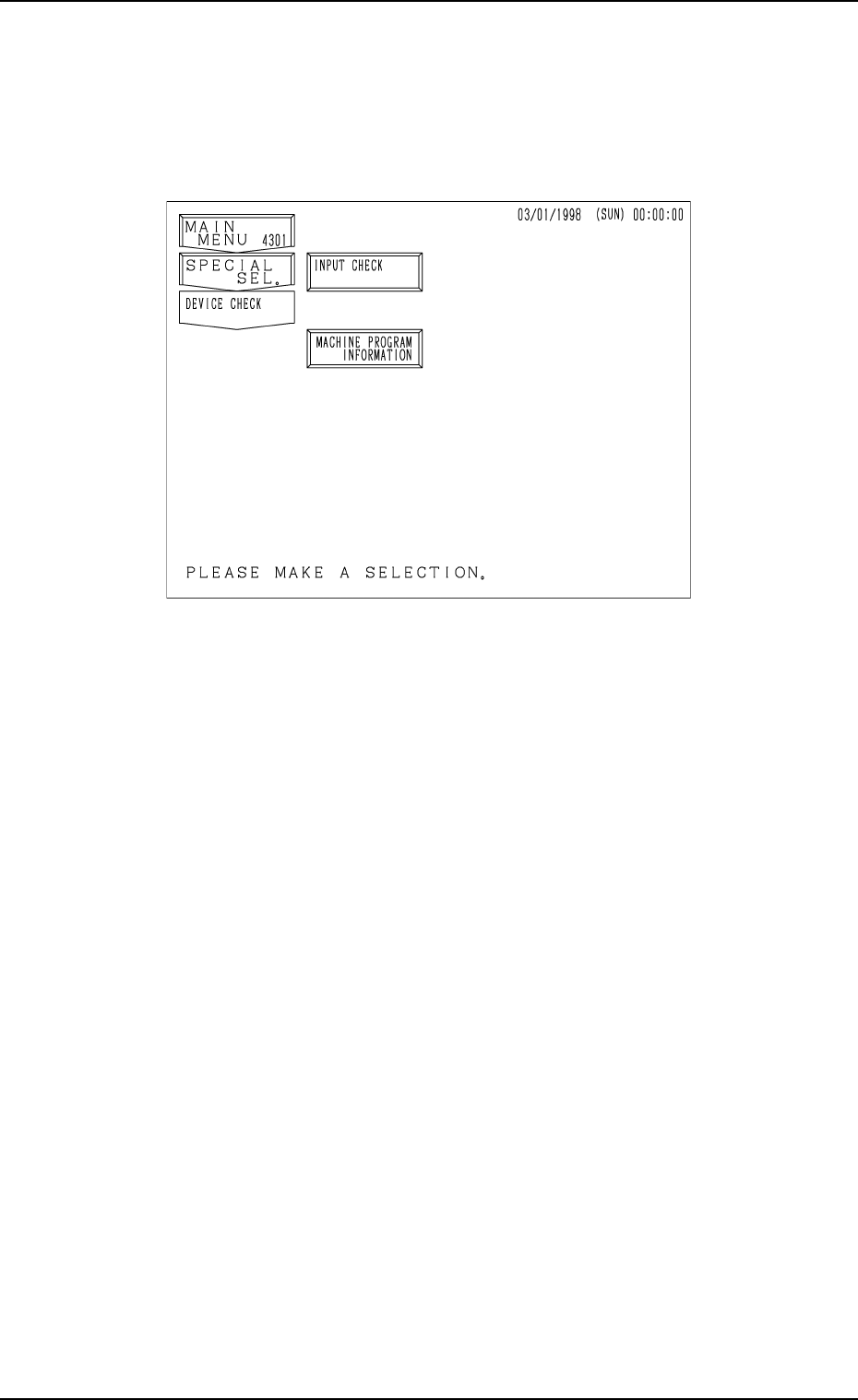
8. DEVICE CHECK Display
When the [DEVICE CHECK] key is pressed at the “SPECIAL SEL.” display,
the following display appears on the screen.
[INPUT CHECK] Key
When this key is pressed, the “INPUT CHECK” display opens, enabling
the checking of input status of various sensors.
[MACHINE PROGRAM INFORMATION] Key
When this key is pressed, the “MACHINE PROGRAM INFORMATION”
display opens, showing software versions of the machine control system.
Fig. 4C331
0305-001 Tg0860-PM-MM
8.1 INPUT CHECK Display
3-159
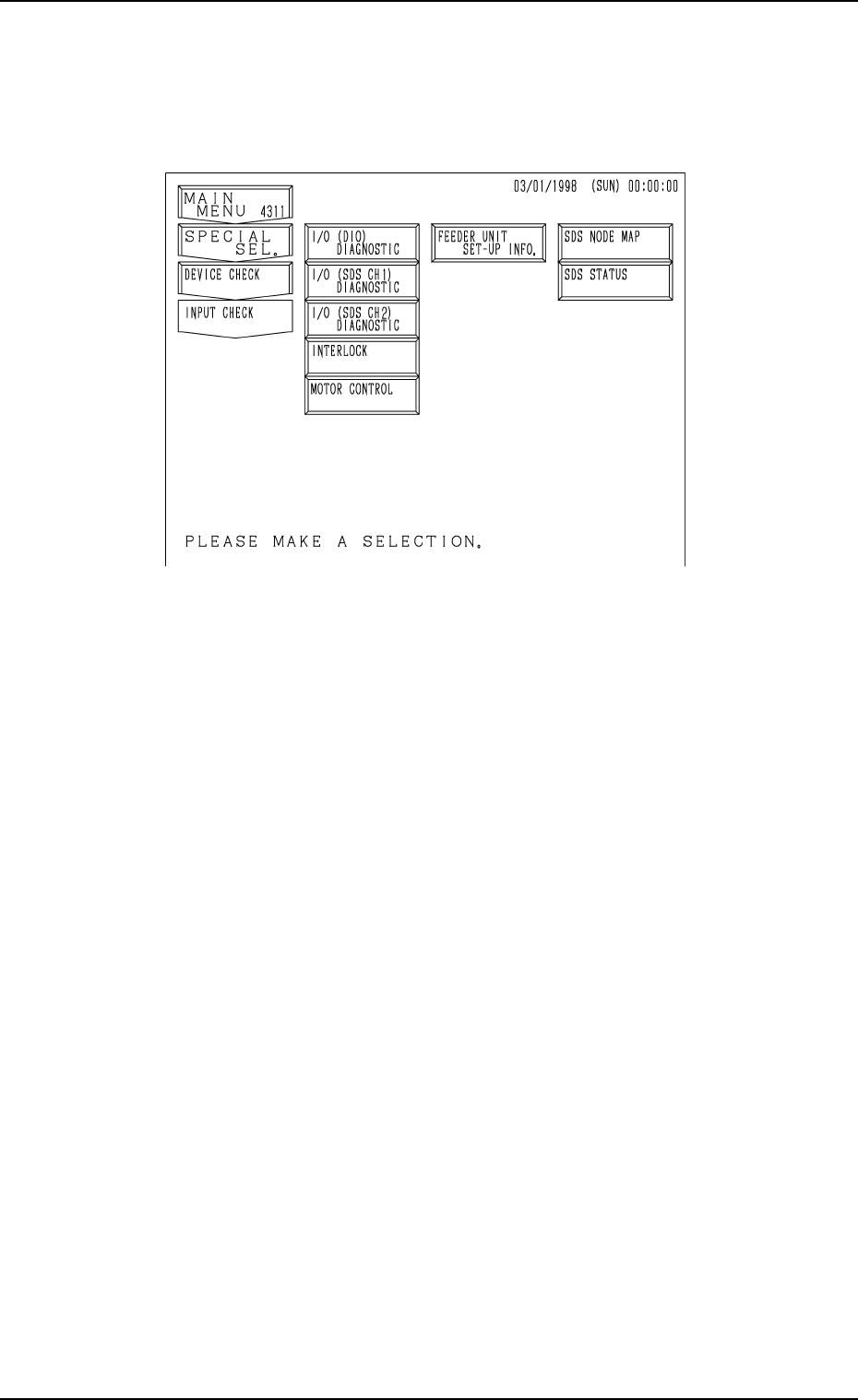
8.1 INPUT CHECK Display
When the [INPUT CHECK] key is pressed at the “DEVICE CHECK” display,
the following display appears on the screen.
[I/O (DIO) DIAGNOSTIC], [I/O (SDS CH 1) DIAGNOSTIC], [I/O (SDS
CH 2) DIAGNOSTIC], [INTERLOCK], and [MOTOR CONTROL] Keys
When one of these keys is pressed, the “INPUT CHECK” display corre-
sponding to the selected key appears on the screen, showing the list of
various ports. When a port No. key is pressed, the status of each bit for
individual ports is displayed.
[SDS NODE MAP] Key
The SDS node map (state of nodes connected to the SDS bus) is displayed.
[SDS STATUS] Key
The SDS status (state of each channel) is displayed.
[FEEDER UNIT SET-UP INFO.] Key
When this key is pressed, the “FEEDER UNIT SET-UP INFORMATION”
display appears on the screen, showing the names of the feeders installed
on the feeder base units #1 through #4.
Fig. 4C332