4OM-1011-002.pdf - 第228页
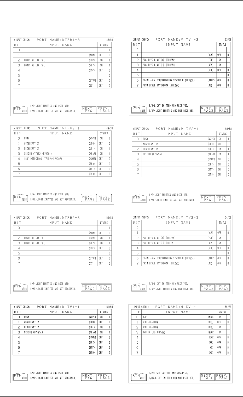
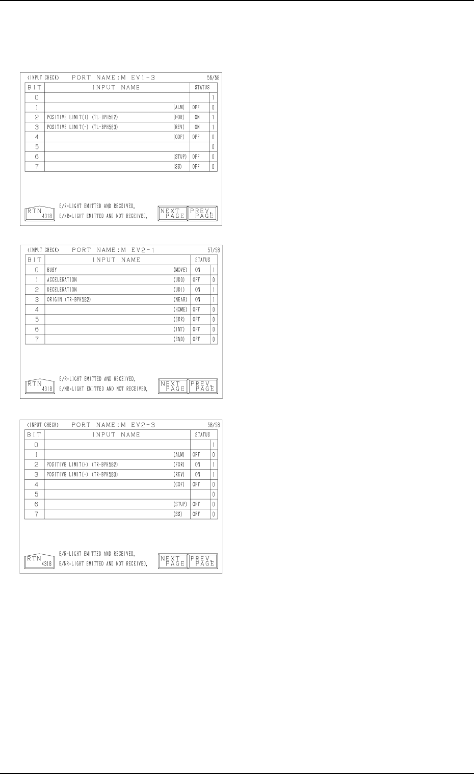
0305-001 Tg0860-PM-MM 8.1 INPUT CHECK Display 3-177 Note: The -marked functions are optional.
0305-001 Tg0860-PM-MM
Note: The -marked functions are optional.
8.1 INPUT CHECK Display
3-176
0305-001 Tg0860-PM-MM
8.1 INPUT CHECK Display
3-177
Note: The -marked functions are optional.
Tg0860-PM-MM
8.1 INPUT CHECK Display
0305-001 3-178
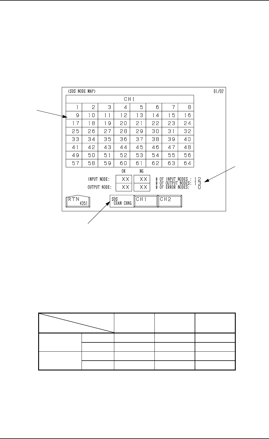
8.1.2 SDS NODE MAP Display
• Shown is the state of the nodes connected to the SDS bus.
When an error is found, check the dip switches of the node P.C.B.
When the [SDS NODE MAP] key is pressed at the “INPUT CHECK” display,
the following display appears on the screen.
*1 “SDS CHAN CHNG” Keys
When the [CH1] key is pressed, Channel 1 is selected. Pressing the [CH2]
key selects Channel 2. The state of the nodes related to the selected channel
is displayed.
*2 State of Nodes
*3 Total of Connected Nodes
Shown are the totals arrived at through the counting of input, output, and
error nodes.
Background
Color
Foreground
Color
Character
Background
Color
Normal Blue White
−
Input Mode
Error Yellow White Blue
Normal Red White
−
Output Mode
Error Yellow White Red
Table 4C4
*3
*1
*2
Fig. 4C333