4OM-1011-002.pdf - 第230页
Tg0860-PM-MM 8.1 INPUT CHECK Display 0305-001 3-179 8.1.3 SDS ST A TUS Display • Shown is the state of each channel. This display is prepared only for a service personnel. When the [SDS ST A TUS] key is pressed at the “I…
Tg0860-PM-MM
8.1 INPUT CHECK Display
0305-001 3-178
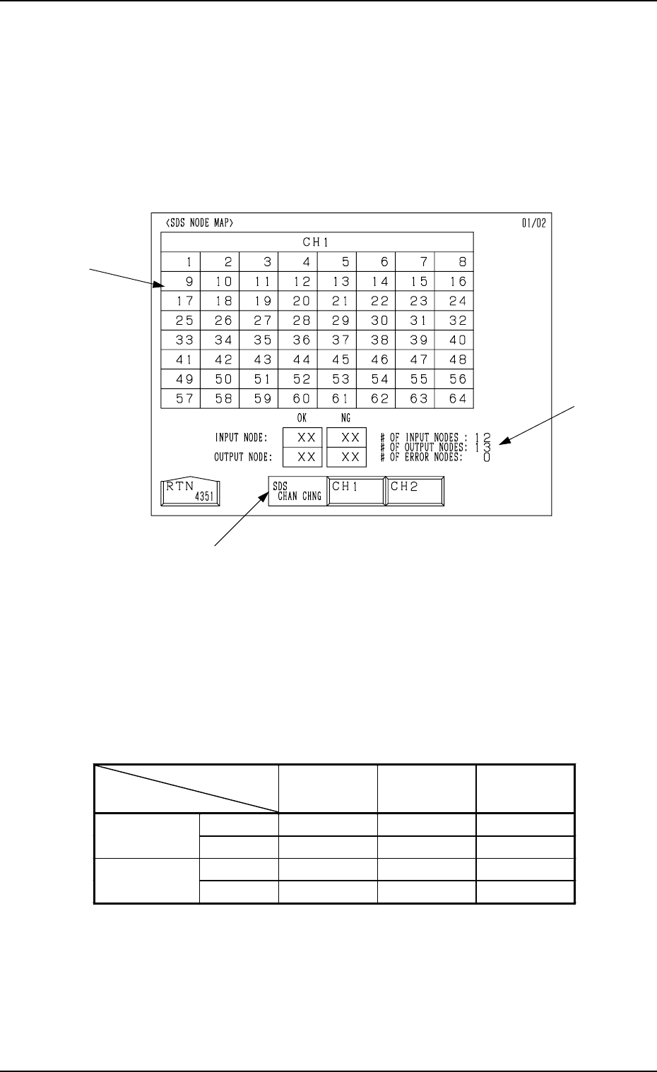
8.1.2 SDS NODE MAP Display
• Shown is the state of the nodes connected to the SDS bus.
When an error is found, check the dip switches of the node P.C.B.
When the [SDS NODE MAP] key is pressed at the “INPUT CHECK” display,
the following display appears on the screen.
*1 “SDS CHAN CHNG” Keys
When the [CH1] key is pressed, Channel 1 is selected. Pressing the [CH2]
key selects Channel 2. The state of the nodes related to the selected channel
is displayed.
*2 State of Nodes
*3 Total of Connected Nodes
Shown are the totals arrived at through the counting of input, output, and
error nodes.
Background
Color
Foreground
Color
Character
Background
Color
Normal Blue White
−
Input Mode
Error Yellow White Blue
Normal Red White
−
Output Mode
Error Yellow White Red
Table 4C4
*3
*1
*2
Fig. 4C333
Tg0860-PM-MM
8.1 INPUT CHECK Display
0305-001 3-179
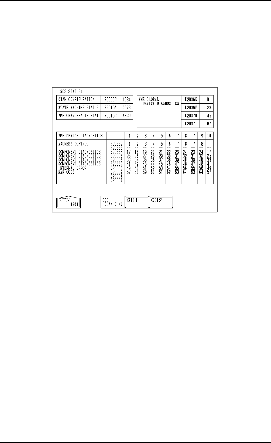
8.1.3 SDS STATUS Display
• Shown is the state of each channel.
This display is prepared only for a service personnel.
When the [SDS STATUS] key is pressed at the “INPUT CHECK” display, the
following display appears on the screen.
Fig. 4C334
Tg0860-PM-MM
8.1 INPUT CHECK Display
0305-001 3-180
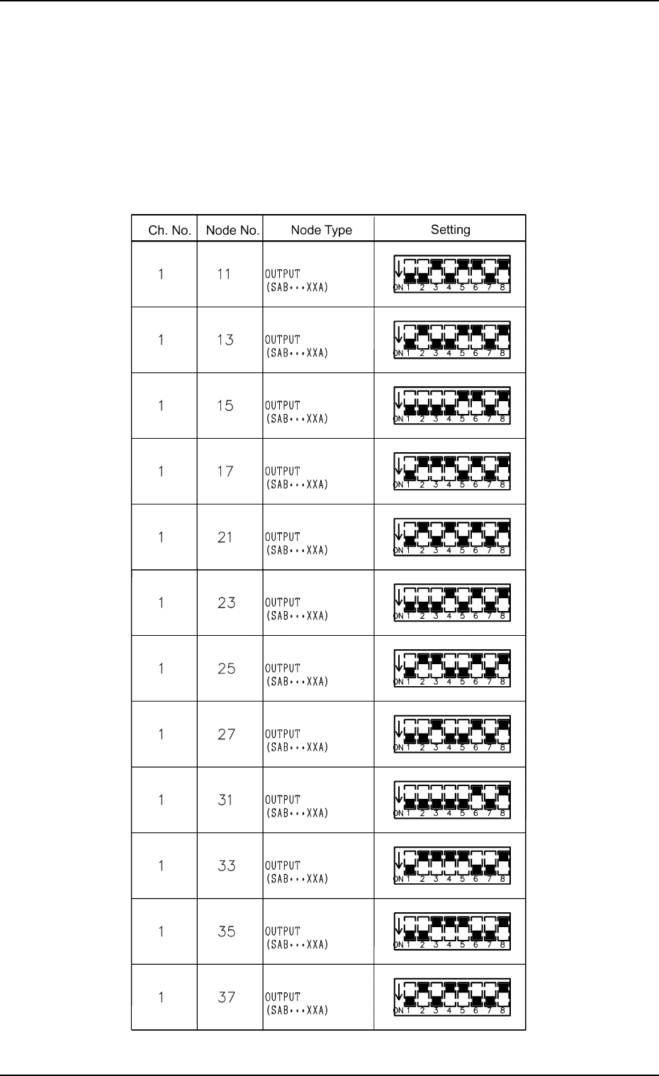
8.1.4 Setting of SDS Nodes
Notes: (a) If the dip switches are not set correctly, normal performance will
not be expected.
(b) Note that the dip switches may be oriented differently.
Setting of SDS Output Nodes (Main Body)
Table 4C5