4OM-1011-002.pdf - 第238页
0305-001 Tg0860-PM-MM 9. UNIT ADJUSTMENT Display When the [UNIT ADJUSTMENT] key is pressed at the “SPECIAL SEL.” display , the following display appears on the screen. [CONVEYOR TIMER ADJUSTMENT] Key When this key is p…
0305-001 Tg0860-PM-MM
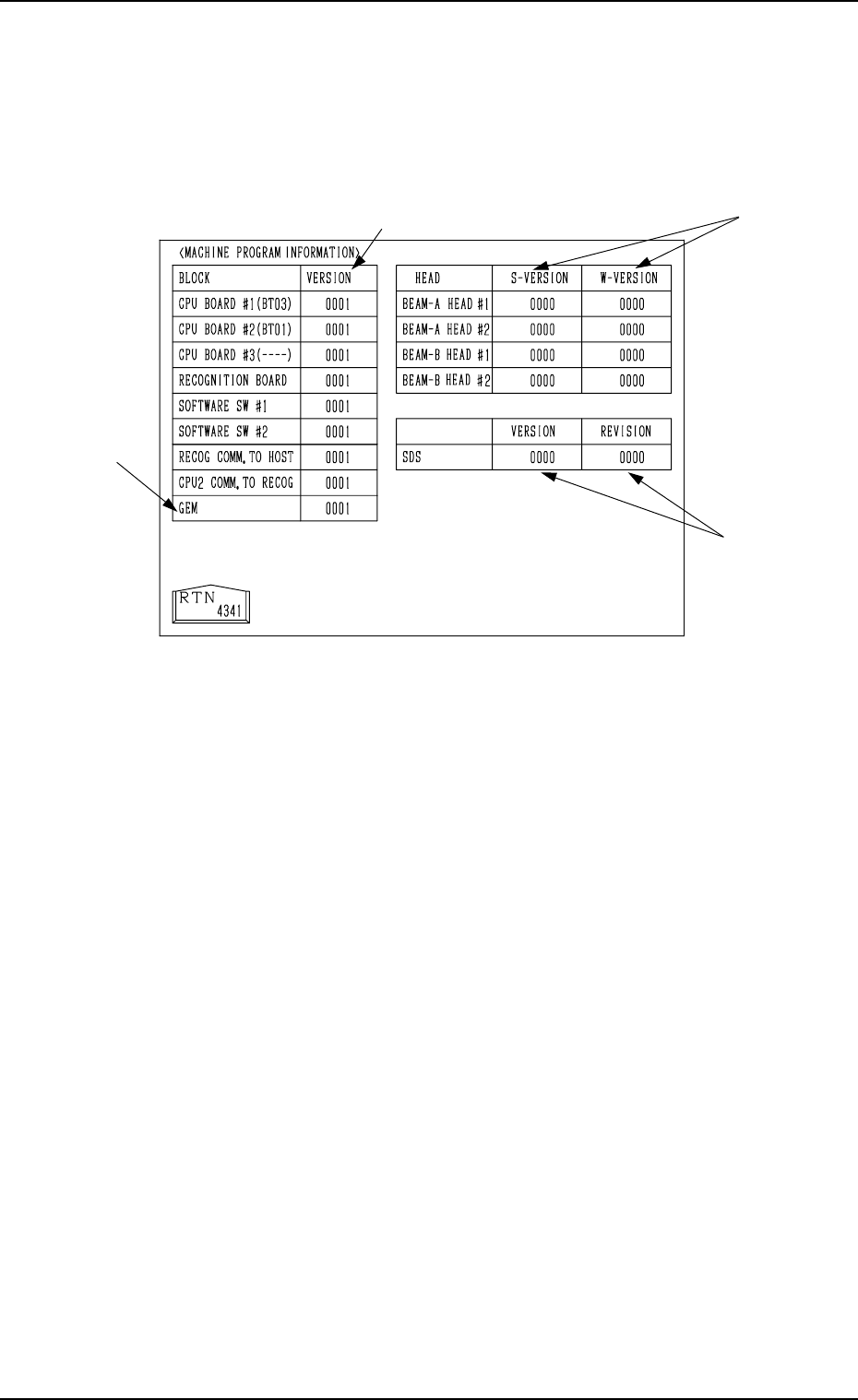
8.2 MACHINE PROGRAM INFORMATION Display
When the [MACHINE PROGRAM INFORMATION] key is pressed at the
“DEVICE CHECK” display, the following display appears on the screen.
Note: The -marked item is optional.
• Software versions of the machine control system are displayed in A-marked
text boxes.
CPU BOARD #1 : Version of Software which controls the op-
eration system.
CPU BOARD #2 : Version of Software which controls the me-
chanical system.
CPU BOARD #3 : Version of Software which controls the multi-
layer tray feeder.
RECOGNITION BOARD : Software Version for Recognition System
SOFTWARE SW #1, #2 : Version of ROM Switches for Distinction of
Options
RECOG COMM. TO HOST: Software Version for Communication be-
tween Recognition and Host Computer
CPU2 COMM. TO RECOG: Software Version for Communication be-
tween Control and Recognition
GEM : Software Version of GEM System (Option)
• Software versions of the placement heads (ZA1, ZA2, ZB1, ZB2 axis) are
displayed in the B-marked text boxes.
S-VERSION : Version of Software for Head Motor Drivers
W-VERSION : Version of Waveforms for Head Motor Drivers
Note: “----” appears in the text box for a head where a communication error
has occurred during version reading.
• Software versions of the SDS (Serial I/O Interface) P.C.B. are displayed in
the C-marked text boxes.
VERSION : Main Version
REVISION : Minor Version (Minute Correction Record No.)
8.2 MACHINE PROGRAM INFORMATION Display
3-186
A
B
C
Fig. 4C336
0305-001 Tg0860-PM-MM
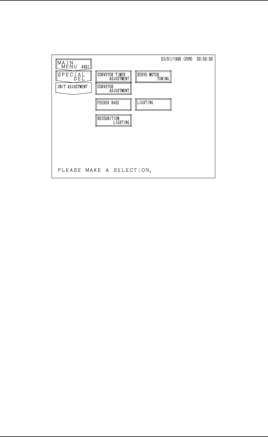
9. UNIT ADJUSTMENT Display
When the [UNIT ADJUSTMENT] key is pressed at the “SPECIAL SEL.”
display, the following display appears on the screen.
[CONVEYOR TIMER ADJUSTMENT] Key
When this key is pressed, the “CONVEYOR TIMER ADJUSTMENT” dis-
play appears on the screen, enabling to change the parameters related to the
conveyor timer for an operation test.
The set parameters for the timer are reflected on actual transfer operations.
[CONVEYOR ADJUSTMENT] Key
When this key is pressed, the “CONVEYOR ADJUSTMENT” display ap-
pears on the screen, enabling the operation of the conveyor motor.
[FEEDER BASE] Key
When this key is pressed, the “FEEDER BASE” display appears on the
screen, enabling an operation test on the feeder base.
■ [RECOGNITION LIGHTING] Key
When this key is pressed, the “RECOGNITION LIGHTING” display ap-
pears on the screen, enabling illumination tests on the lamps for the P.E.C.
and component recognition systems.
[SERVO MOTOR TUNING] Key
When this key is pressed, the “SERVO MOTOR TUNING” display ap-
pears on the screen, enabling to set the working speed of each servomotor
shaft for an operation test.
Note: This display is prepared only for a service personnel. No operation
is required.
[LIGHTING] Key
When this key is pressed, the “LIGHTING” display appears on the screen,
enabling the teaching operation of various lighting systems.
Note: This display is prepared only for a service personnel. No operation
is required.
9. UNIT ADJUSTMENT Display
3-187
Fig. 4C337
0305-001 Tg0860-PM-MM
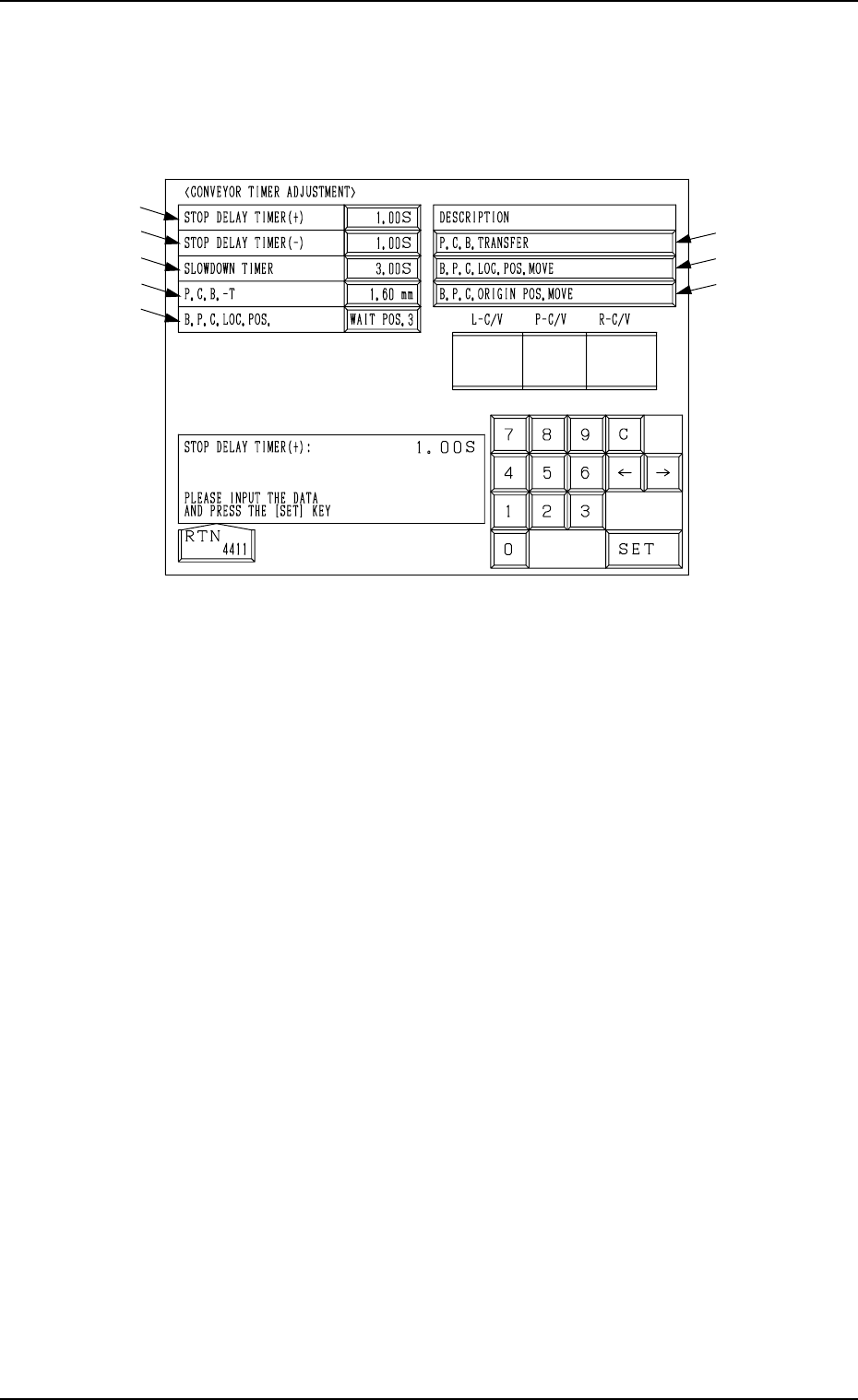
9.1 CONVEYOR TIMER ADJUSTMENT Display
When the [CONVEYOR TIMER ADJUSTMENT] key is pressed at the “UNIT
ADJUSTMENT” display, the following display appears on the screen.
Parameters related to various operation timers can be set, enabling a test on
transfer operations.
*1 STOP DELAY TIMER (+)
When a P.C.B. is positioned at the P.C.B. positioning section (P conveyor
moving forward), this timer is used to correct the position where the P.C.B.
should be stopped.
Set the period of time (time of the delay timer) during which the location of
the P.C.B. detection sensor (BPH144) is detected and the motor is stopped
for P.C.B. positioning.
This parameter (the value for the timer) must be adjusted to ensure that a
P.C.B. comes to the P.C.B. stopper position and stops there.
●
Standard Value
0.25 seconds
*2 STOP DELAY TIMER (−)
When a P.C.B. is positioned at the P.C.B. positioning section (P conveyor
moving backward), this timer is used to correct the position where the P.C.B.
should be stopped.
Set the period of time (time of the delay timer) during which the location of
the P.C.B. detection sensor (BPH144) is detected and the motor is stopped
for P.C.B. positioning.
This parameter (the value for the timer) must be adjusted to ensure that a
P.C.B. comes to the P.C.B. stopper position and stops there.
• Standard Value
0.25 seconds
*3 SLOWDOWN TIMER
Set the period of time in which the transfer speed should be slowed down
while P.C.B.’s are being transferred at high speed from the input conveyor
to the P.C.B. positioning section.
• Standard Value
0.76 seconds
9.1 CONVEYOR TIMER ADJUSTMENT Display
*1
*2
*3
*4
*5
*8
*7
*6
Fig. 4C338
3-188