4OM-1011-002.pdf - 第239页
0305-001 Tg0860-PM-MM 9.1 CONVEYOR TIMER ADJUSTMENT Display When the [CONVEYOR TIMER ADJUSTMENT] key is pressed at the “UNIT ADJUSTMENT” display , the following display appears on the screen. Parameters related to variou…
0305-001 Tg0860-PM-MM
9. UNIT ADJUSTMENT Display
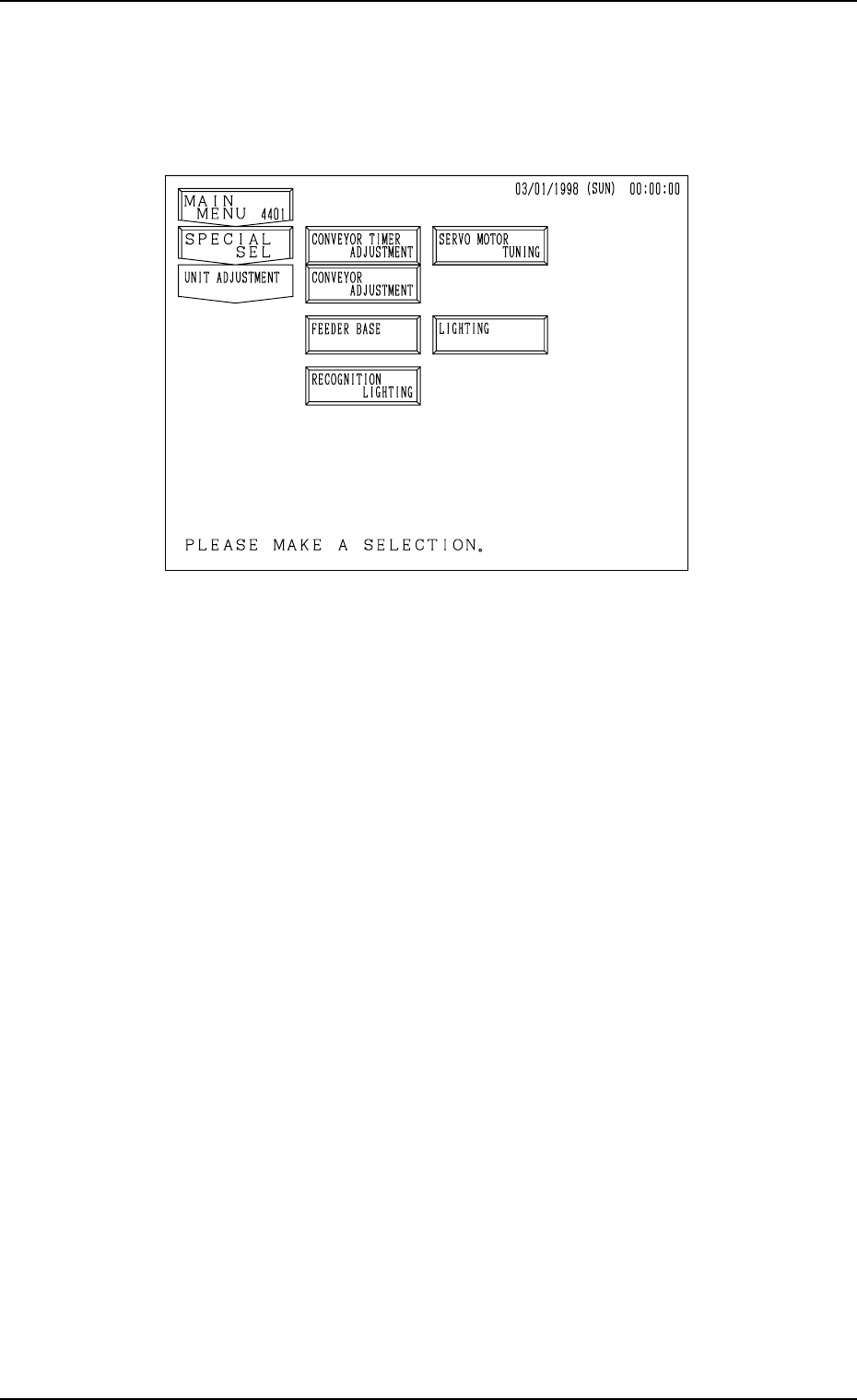
When the [UNIT ADJUSTMENT] key is pressed at the “SPECIAL SEL.”
display, the following display appears on the screen.
[CONVEYOR TIMER ADJUSTMENT] Key
When this key is pressed, the “CONVEYOR TIMER ADJUSTMENT” dis-
play appears on the screen, enabling to change the parameters related to the
conveyor timer for an operation test.
The set parameters for the timer are reflected on actual transfer operations.
[CONVEYOR ADJUSTMENT] Key
When this key is pressed, the “CONVEYOR ADJUSTMENT” display ap-
pears on the screen, enabling the operation of the conveyor motor.
[FEEDER BASE] Key
When this key is pressed, the “FEEDER BASE” display appears on the
screen, enabling an operation test on the feeder base.
■ [RECOGNITION LIGHTING] Key
When this key is pressed, the “RECOGNITION LIGHTING” display ap-
pears on the screen, enabling illumination tests on the lamps for the P.E.C.
and component recognition systems.
[SERVO MOTOR TUNING] Key
When this key is pressed, the “SERVO MOTOR TUNING” display ap-
pears on the screen, enabling to set the working speed of each servomotor
shaft for an operation test.
Note: This display is prepared only for a service personnel. No operation
is required.
[LIGHTING] Key
When this key is pressed, the “LIGHTING” display appears on the screen,
enabling the teaching operation of various lighting systems.
Note: This display is prepared only for a service personnel. No operation
is required.
9. UNIT ADJUSTMENT Display
3-187
Fig. 4C337
0305-001 Tg0860-PM-MM
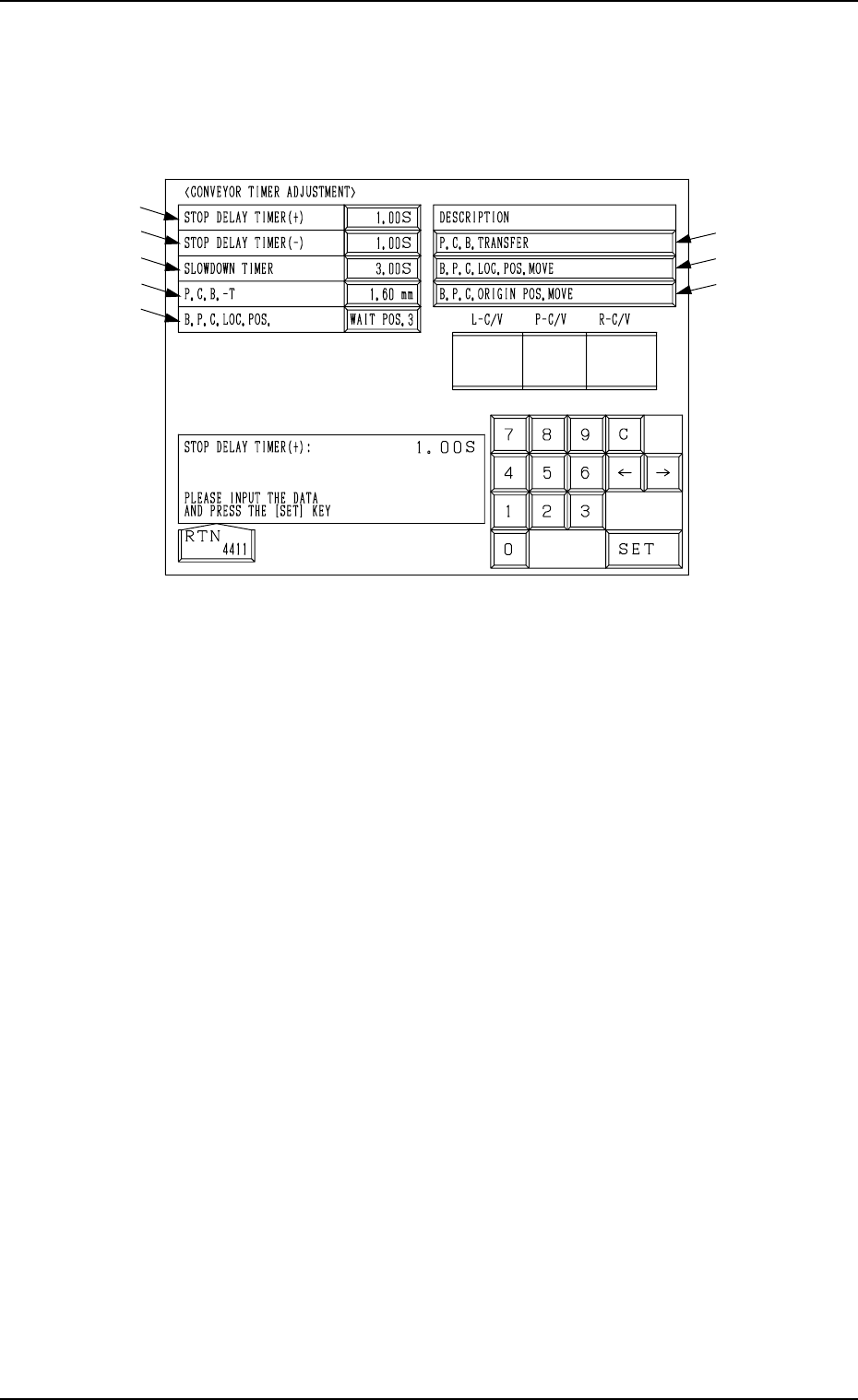
9.1 CONVEYOR TIMER ADJUSTMENT Display
When the [CONVEYOR TIMER ADJUSTMENT] key is pressed at the “UNIT
ADJUSTMENT” display, the following display appears on the screen.
Parameters related to various operation timers can be set, enabling a test on
transfer operations.
*1 STOP DELAY TIMER (+)
When a P.C.B. is positioned at the P.C.B. positioning section (P conveyor
moving forward), this timer is used to correct the position where the P.C.B.
should be stopped.
Set the period of time (time of the delay timer) during which the location of
the P.C.B. detection sensor (BPH144) is detected and the motor is stopped
for P.C.B. positioning.
This parameter (the value for the timer) must be adjusted to ensure that a
P.C.B. comes to the P.C.B. stopper position and stops there.
●
Standard Value
0.25 seconds
*2 STOP DELAY TIMER (−)
When a P.C.B. is positioned at the P.C.B. positioning section (P conveyor
moving backward), this timer is used to correct the position where the P.C.B.
should be stopped.
Set the period of time (time of the delay timer) during which the location of
the P.C.B. detection sensor (BPH144) is detected and the motor is stopped
for P.C.B. positioning.
This parameter (the value for the timer) must be adjusted to ensure that a
P.C.B. comes to the P.C.B. stopper position and stops there.
• Standard Value
0.25 seconds
*3 SLOWDOWN TIMER
Set the period of time in which the transfer speed should be slowed down
while P.C.B.’s are being transferred at high speed from the input conveyor
to the P.C.B. positioning section.
• Standard Value
0.76 seconds
9.1 CONVEYOR TIMER ADJUSTMENT Display
*1
*2
*3
*4
*5
*8
*7
*6
Fig. 4C338
3-188

0305-001 Tg0860-PM-MM
9.1 CONVEYOR TIMER ADJUSTMENT Display
3-189
*4 P.C.B.-T
Set the thickness of the P.C.B. which is used for a transfer test.
• Standard Value
Same Value as P.C.B. Thickness in Current Pattern Program
5 mm when a Current Pattern Program is not Specified
*5 B.P.C. LOC. POS.
“WAIT POS. 1”, “WAIT POS. 2”, or “WAIT POS. 3” can be selected.
WAIT POS. 1 : Set this in the data box when a P.C.B. has no previously-
placed components and is positioned based on “Outline
Reference”.
The backup base ascends to an area near the P.C.B. trans-
fer plane in advance and is set in the standby mode during
P.C.B. tansfer operation.
WAIT POS. 2 : Set this in the data box when the height of a previously-
placed component is less than 6.5 mm.
The backup base ascends to an area near “P.C.B. Transfer
Plane + Previously-Placed Component” in advance and is
set in the standby mode during P.C.B. transfer operation.
WAIT POS. 3 : Set this in the data box when the height of a previously-
placed component is 6.5 mm or more.
The backup base waits at its origin.
The parameters set here become valid only when a transfer test is performed,
using this display.
The standby position during automatic operation is determined according
to the operation data in the pattern program.
• Standard Value
Wait (Standby) Position designated in the current program
“WAIT POS. 3” when the current program is indefinite
*6 [P.C.B. TRANSFER] Key
This key is used to perform the P.C.B. transfer operation after the param-
eters (described in *1 through *5) are set.
When this key is selected and the [MOVE] button is pressed, the machine
performs the P.C.B. transfer and positioning operations.
*7 [B.P.C. LOC. POS. MOVE] Key
When this key is selected and the [MOVE] button is pressed, the backup
base ascends to the point where a P.C.B. is positioned.
*8 [B.P.C. ORIGIN POS. MOVE] Key
When this key is selected and the [MOVE] button is pressed, the backup
base descends to its origin position.