4OM-1011-002.pdf - 第241页
0305-001 Tg0860-PM-MM 9.2 FEEDER BASE Display 3-190 9.2 FEEDER BASE Display When the [FEEDER BASE] key is pressed at the “UNIT ADJUSTMENT” display , the following display appears on the screen. When the [FEEDER BASE # 1]…

0305-001 Tg0860-PM-MM
9.1 CONVEYOR TIMER ADJUSTMENT Display
3-189
*4 P.C.B.-T
Set the thickness of the P.C.B. which is used for a transfer test.
• Standard Value
Same Value as P.C.B. Thickness in Current Pattern Program
5 mm when a Current Pattern Program is not Specified
*5 B.P.C. LOC. POS.
“WAIT POS. 1”, “WAIT POS. 2”, or “WAIT POS. 3” can be selected.
WAIT POS. 1 : Set this in the data box when a P.C.B. has no previously-
placed components and is positioned based on “Outline
Reference”.
The backup base ascends to an area near the P.C.B. trans-
fer plane in advance and is set in the standby mode during
P.C.B. tansfer operation.
WAIT POS. 2 : Set this in the data box when the height of a previously-
placed component is less than 6.5 mm.
The backup base ascends to an area near “P.C.B. Transfer
Plane + Previously-Placed Component” in advance and is
set in the standby mode during P.C.B. transfer operation.
WAIT POS. 3 : Set this in the data box when the height of a previously-
placed component is 6.5 mm or more.
The backup base waits at its origin.
The parameters set here become valid only when a transfer test is performed,
using this display.
The standby position during automatic operation is determined according
to the operation data in the pattern program.
• Standard Value
Wait (Standby) Position designated in the current program
“WAIT POS. 3” when the current program is indefinite
*6 [P.C.B. TRANSFER] Key
This key is used to perform the P.C.B. transfer operation after the param-
eters (described in *1 through *5) are set.
When this key is selected and the [MOVE] button is pressed, the machine
performs the P.C.B. transfer and positioning operations.
*7 [B.P.C. LOC. POS. MOVE] Key
When this key is selected and the [MOVE] button is pressed, the backup
base ascends to the point where a P.C.B. is positioned.
*8 [B.P.C. ORIGIN POS. MOVE] Key
When this key is selected and the [MOVE] button is pressed, the backup
base descends to its origin position.
0305-001 Tg0860-PM-MM
9.2 FEEDER BASE Display
3-190
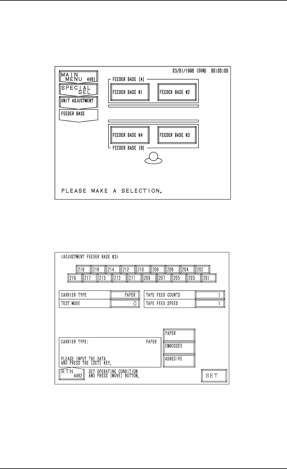
9.2 FEEDER BASE Display
When the [FEEDER BASE] key is pressed at the “UNIT ADJUSTMENT”
display, the following display appears on the screen.
When the [FEEDER BASE #1], the [FEEDER BASE #2], the [FEEDER BASE
#3], or the [FEEDER BASE #4] key is pressed, the corresponding display such
as the following dispiay appears on the screen.
“ADJUSTMENT FEEDER BASE
##
##
#3” Display
Fig. 4C340
Fig. 4C339

0305-001 Tg0860-PM-MM
CARRIER TYPE
Set the type of a carrier tape in the data box.
“PAPER”, “EMBOSSED”, or “ADHESIVE” can be selected.
TEST MODE
Set “0” (zero) in the data box.
TAPE FEED COUNTS
Set the number of tape feeding times in the data box.
The number of tape feeding times means how many times tape feeding
actions are taken.
In normal cases, set “1” in the data box.
When the selected carrier tape has to be fed more than once due to the
relation between the feed pitch and speed, set the required number of tape
feeding times.
TAPE FEED SPEED
Set the tape feeding speed in the data box.
Operation Procedure
(1) Set a parameter in each data box.
(2) Select the No. key of the feeder to be activated.
When the [MOVE] button is pressed, the selected feeder starts moving
forward.
Ref.: Two feeder Nos. can be selected at the same time to simultaneously
move the two feeders forward.
9.2 FEEDER BASE Display
3-191