4OM-1011-002.pdf - 第246页
0305-001 Tg0860-PM-MM 9.4 RECOGNITION LIGHTING Display 3-195 9.4.1 COMPONENT RECOG LIGHTING Display When the [COMPONENT RECOG LIGHTING] key is pressed at the “REC- OGNITION LIGHTING” display , the following display appea…
0305-001 Tg0860-PM-MM
9.4 RECOGNITION LIGHTING Display
3-194
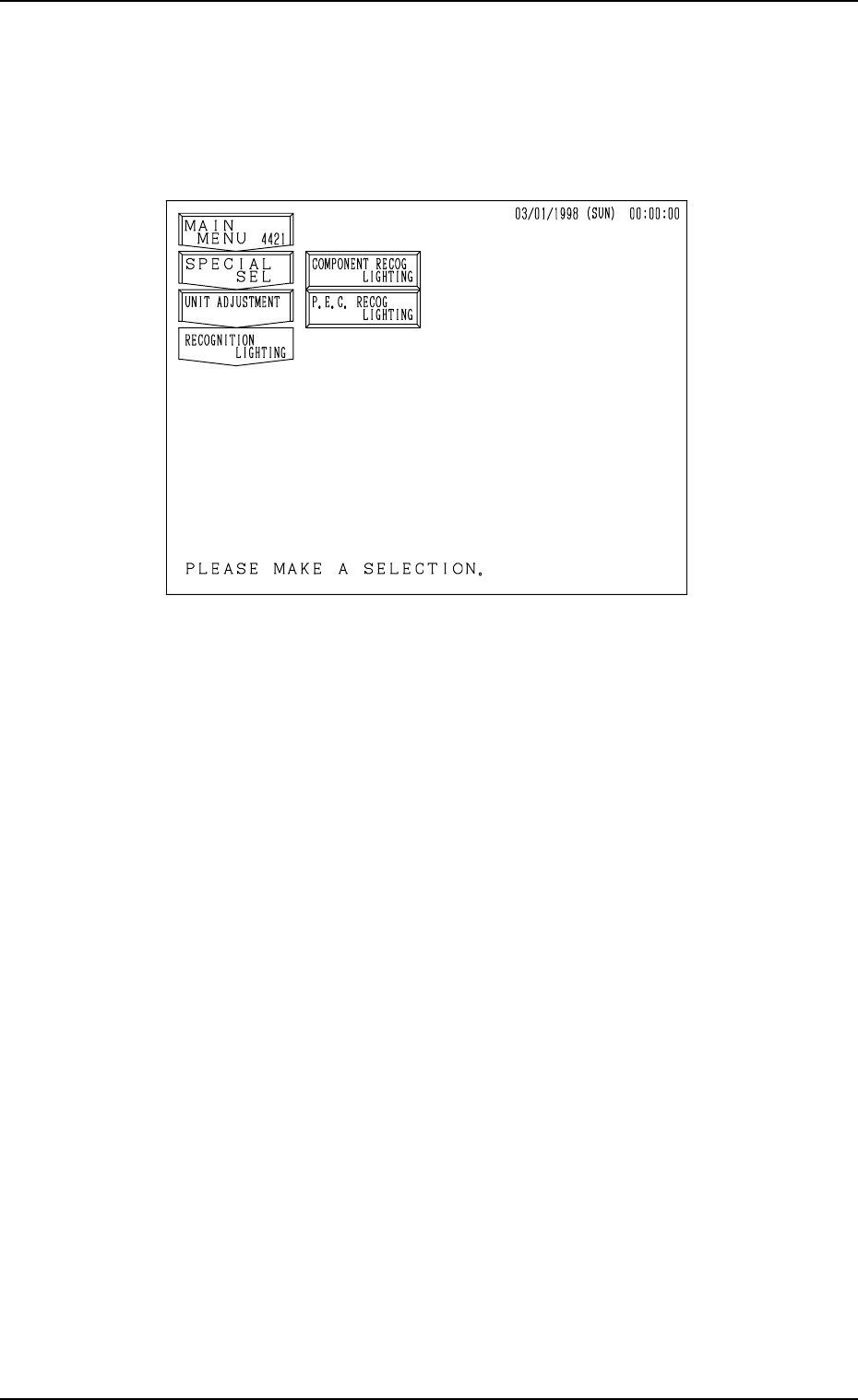
9.4 RECOGNITION LIGHTING Display
When the [RECOGNITION LIGHTING] key is pressed at the “UNIT AD-
JUSTMENT” display, the following display appears on the screen.
[COMPONENT RECOG LIGHTING] Key
When this key is pressed, the “COMPONENT RECOG LIGHTING” dis-
play appears on the screen, enabling the illumination check operations in
each individual blocks for component recognition lighting.
[P.E.C. RECOG LIGHTING] Key
When this key is pressed, the “P.E.C. RECOG LIGHTING” display ap-
pears on the screen, enabling the illumination check operations for P.E.C.
recognition lighting.
Fig. 4C343
0305-001 Tg0860-PM-MM
9.4 RECOGNITION LIGHTING Display
3-195
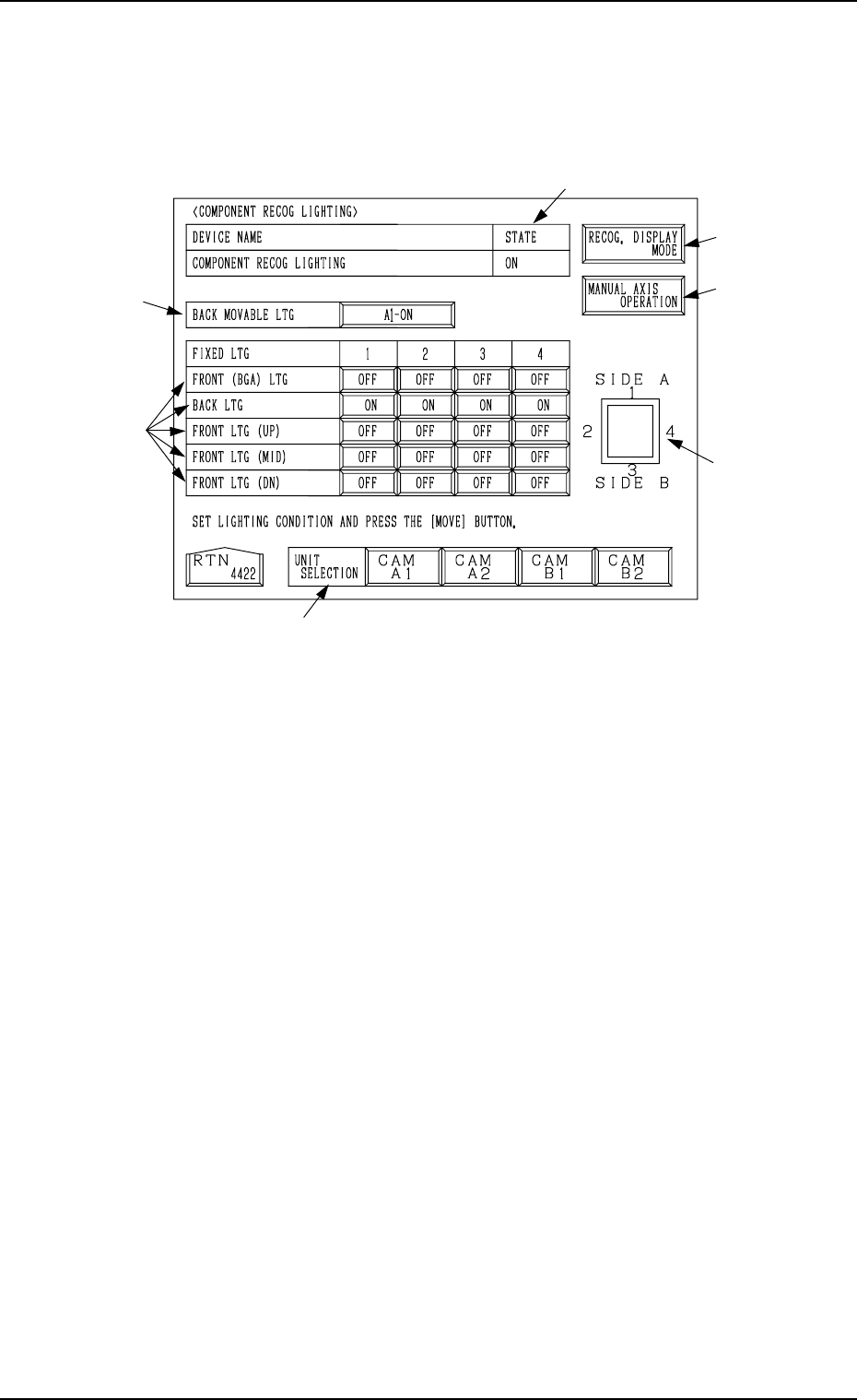
9.4.1 COMPONENT RECOG LIGHTING Display
When the [COMPONENT RECOG LIGHTING] key is pressed at the “REC-
OGNITION LIGHTING” display, the following display appears on the screen.
When the [MOVE] button is pressed after the following items *1, *2, and *3
are set, the lamps for component recognition can be turned ON.
*1 UNIT SELECTION
Select a unit for which the lamps for component recognition lighting must
be turned ON.
The [CAM A1], the [CAM A2], the [CAM B1], or the [CAM B2] key can
be selected.
*2 BACK MOVABLE LTG
Every time the key beside this label is pressed, the expression on the key
changes in the order “OFF” → “A1-ON” → “A2-ON” → “B1-ON” →
“B2-ON”.
*3 FRONT (BGA) LTG, BACK LTG, FRONT LTG (UP), FRONT LTG
(MID), and FRONT LTG (DN)
Press the keys corresponding to the directions 1, 2, 3, and 4 of each unit to
set “OFF” or “ON” individually.
Indicated in *4 are the directions which correspond to the labels “1”, “2”,
“3”, and “4”.
*4 Shown is the positional relation for component recognition lighting.
*5 STATE
Shown is the state "ON" or "OFF" of the lamps for component recognition
lighting.
*2
*3
*1
*6
*4
*7
*5
Fig. 4C344
0305-001 Tg0860-PM-MM
9.4 RECOGNITION LIGHTING Display
3-196
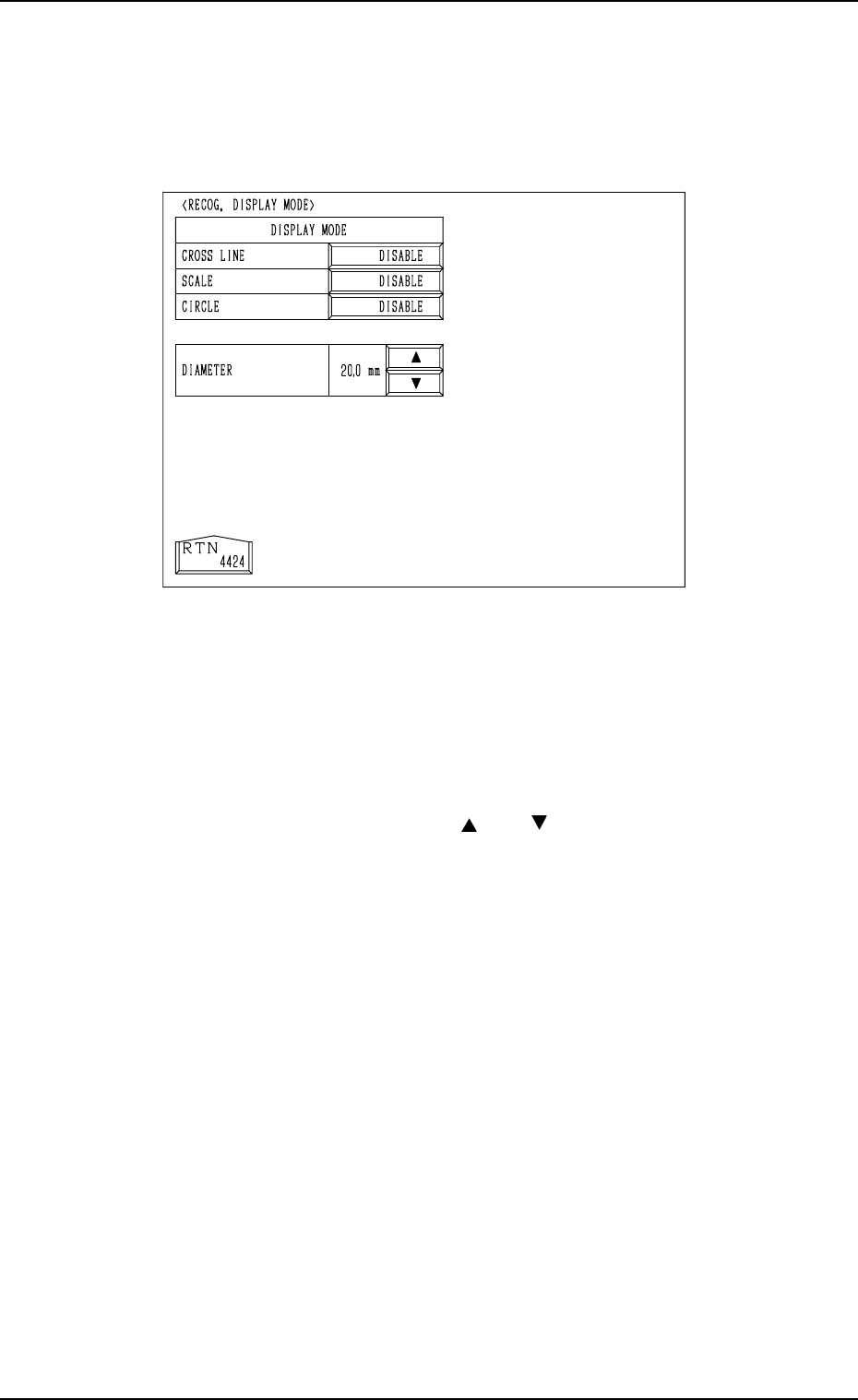
*6 [RECOG. DISPLAY MODE] Key
When this key is pressed, the “RECOG. DISPLAY MODE” display (Fig.
4C345) appears on the screen, enabling the setting of the display mode for
the recognition monitor.
“ENABLE” or “DISABLE” can be set in each data box. For example, when
“ENABLE” is set in the “CROSS LINE” data box, crosslines appear on the
recognition monitor. The same applies to “SCALE” and “CIRCLE”.
When “ENABLE” is set in the “CIRCLE” data box, specify the diameter in
the “DIAMETER” text box.
By pressing the scroll arrow boxes ([ ] and [ ]), the diameter of the circle
can be changed.
*7 [MANUAL AXIS OPERATION] Key
When this key is pressed, the “MANUAL AXIS OPERATION” display
appears on the screen, enabling the manual axis operation of each indi-
vidual devices.
The operation is the same as the manual axis operation performed through
manual operations.
Refer to “7. Manual Axis Operation of Section 4 in Volume 1” for details.
Fig. 4C345