4OM-1011-002.pdf - 第268页
0305-001 Tg0860-PM-MM 3. Management of Password This machine is provided with a password function which can be implemented on specific data editing, preventing various types of data groups in the ma- chine from being del…
0305-001 Tg0860-PM-MM
2. MACHINE SET-UP Display
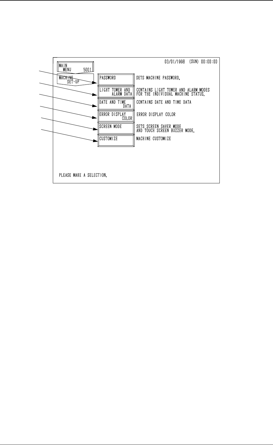
When the [MACHINE SET-UP] key is pressed at the “MAIN MENU” dis-
play, the following display appears on the screen.
*1 When this key is pressed, the “PASSWORD” display appears on the screen.
Three kinds of passwords and an effective range of each password can be
set. Deleting or changing data on the machine side by mistake can be avoided
by setting and managing a password.
*2 When this key is pressed, the “LIGHT TOWER AND ALARM DATA”
display appears on the screen.
The “ON, OFF, or FL (flashing)” can be selected for the tower lights ac-
cording to the machine status (automatic operation mode, error condition,
P.C.B. transfer waiting mode, etc.).
The “ON (CONTINUOUS), OFF, ON AND OFF, or OPTIONAL ALARM”
can also be selected for the alarm buzzer according to the machine status
(error condition, shortage of component, alternate feeder, etc.).
*3 When this key is pressed, the “DATE AND TIME DATA” display appears
on the screen.
Date and time (calendar function) can be set.
*4 When this key is pressed, the “ERROR DISPLAY COLOR” display ap-
pears on the screen.
The background and letter colors of the error information box can be changed
according to one of the several optional combinations.
*5 When this key is pressed, the “SCREEN MODE” display appears on the
screen.
This function is used to turn the touch screen buzzer “ON” or “OFF” and
set the screen saver mode. Settings such as date (three kinds of expres-
sions), Japanese/English, metric/inch system can also be controlled.
Note: This display can’t be opend when the machine is working or
communicateing with the programming device (option).
*6 When this key is pressed, the “CUSTOMIZE” display appears on the screen.
This function is used to automatically delete all component library data
which is not used by the machine after the corresponding pattern program
data is deleted.
4-2
2. MACHINE SET-UP Display
Fig. 4D2
*1
*2
*3
*4
*5
*6
0305-001 Tg0860-PM-MM
3. Management of Password
This machine is provided with a password function which can be implemented
on specific data editing, preventing various types of data groups in the ma-
chine from being deleted by mistake and keeping unauthorized user (third party)
from not only editing data but also operating the machine.
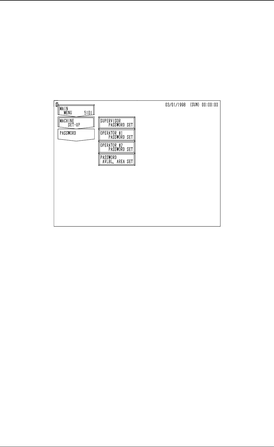
When the [PASSWORD] key is pressed at the “MACHINE SET-UP” display,
the following display appears on the screen.
• The following three kinds of passwords can be set.
SUPERVISOR PASSWORD SET (1st Priority)
OPERATOR #1 PASSWORD SET (2nd Priority)
OPERATOR #2 PASSWORD SET (3rd Priority)
Each password can be set for the supervisor, the operator assigned as #1,
and the operator assigned as #2.
• Available areas for each password can also be allocated, preventing certain
areas from being logged in. For example, by allocating a certain password
for the operator #1 to let the system allow him to both edit data and operate
the machine if he can enter the specified password correctly. On the other
hand, by specifying a password for the operator #2, the system allows him
to operate the machine only.
Notes: (a) Only the personnel designated as a supervisor has the right to set
passwords and available areas.
(b) Although the machine can be operated without setting any pass-
word, it is advisable that at least a password for the supervisor
should be set. If a third party sets a password, the machine cannot
be operated by any other personnel.
(c) When the supervisor forgets his/her password, it becomes impos-
sible to set any passwords and available areas.
To make the password function available again, all memory must
be cleared.
4-3
3. Management of Password
Fig. 4D3
0305-001 Tg0860-PM-MM
3.1 Setting of Password Available Areas
(1) Enter the password specified as one for the supervisor to issue the “Log
In” command.
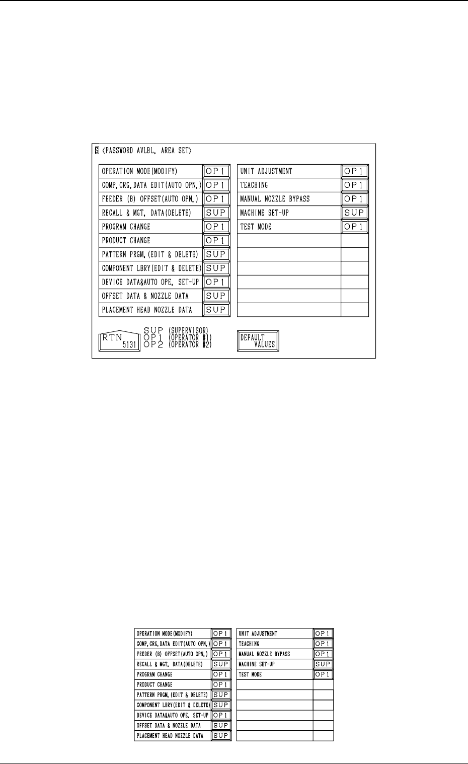
(2) Open the “PASSWORD AVLBL. AREA SET” display (Fig. 4.3). (Hier-
archical Sequence : “MAIN MENU” Display → “MACHINE SET-UP”
Display → “PASSWORD” Display → “PASSWORD AVLBL. AREA
SET” Display)
(3) Set “SUP”, “OP1”, or “OP2” in the data box of each label (items for
which a password type can be allocated). Every time the data box is
pressed, the system allows you to scroll up and down the range of options
(“SUP” → “OP1” → “OP2”).
[SUP]: Operation possible only when the supervisor can success-
fully log on to the system using the supervisor password.
[OP1]: Operation possible only when the supervisor or the opera-
tor #1 can successfully log on to the system using each pass-
word.
[OP2] : Operation possible only when the supervisor, the operator
#1, or the operator #2 can successfully log on to the system
using each password.
Notes: (a) When an operator other than the supervisor issues the “Log
In” command, he cannot set any password available area
but can check how the passwords are set for each function.
(b) It is possible to set password available areas even when
each password is not set.
• When the [DEFAULT VALUES] key is pressed, the default values are
set in each data boxes. The following figure shows the default values.
4-4
3.1 Setting of Password Available Areas
Fig. 4D4
Fig. 4D5