4OM-1011-002.pdf - 第286页
0305-001 Tg0860-PM-MM [DEF AUL T V ALUES] Key When this key is pressed, each parameter is reset to its default. • When images on the screen appear in bad shape due to the set parameters and cannot be adjusted, press the …

0305-001 Tg0860-PM-MM
PHASE ADJUSTMENT 1
Set a parameter to change the phase of the sampling clock for better picture
quality.
Enter “0” or “1” in the data box.
The standard value is “0”.
PHASE ADJUSTMENT 2
Set a parameter to change the phase of the sampling clock for better picture
quality.
Enter “0” or “1” in the data box.
The standard value is “0”.
PHASE ADJUSTMENT 3
Set a parameter to change the phase of the sampling clock for better picture
quality.
Enter “0” or “1” in the data box.
The standard value is “0”.
PHASE ADJUSTMENT 4
Set a parameter to change the phase of the sampling clock for better picture
quality.
Enter “0” or “1” in the data box.
The standard value is “0”.
DOT CLOCK
Select the VC0 circuit (high frequency circuit) to reduce the difference in
the dot clock (image frequency = bit rate) which depends on the host com-
puter being used.
The standard value is “1”.
Change the parameters set in the “PHASE ADJUSTMENT 1”, “PHASE
ADJUSTMENT 2”, “PHASE ADJUSTMENT 3”, “PHASE ADJUST-
MENT 4” and “DOT CLOCK” data boxes such that the marks (
)
located at the four corners should not flicker and the color should not be
mottled or blurred.
DELAY ADJUSTMENT 1
Set a parameter to delay the sampling clock supplied to the LCD.
Enter “0” to “7” in the data box.
The standard value is “0”.
Note: Do not change the setting unless necessary. Otherwise, images on
the screen will appear in bad shape.
DELAY ADJUSTMENT 2
Set a parameter to delay the sampling clock supplied to the counter circuit.
Enter “0” to “7” in the data box.
The standard value is “0”.
Note: Do not change the setting unless necessary. Otherwise, images on
the screen will appear in bad shape.
BACKLIGHT ADJUSTMENT
Set a parameter to adjust the brightness of the back light.
“0” is the minimum value and “3” the maximum, representing the bright-
ness.
It takes a few minutes before the brightness of CFL (cold-cathode tube)
becomes stable after the illumination. When the brightness becomes stable,
adjust the brightness of the back light.
The standard value is “3”.
5-2
1. SCREEN ADJUSTMENT Display

0305-001 Tg0860-PM-MM
[DEFAULT VALUES] Key
When this key is pressed, each parameter is reset to its default.
•
When images on the screen appear in bad shape due to the set parameters
and cannot be adjusted, press the [RESET] button. The previous condi-
tion resumes only once. (Undo Function)
When the [RESET] button is pressed again, the original condition (the
condition before “Undo” operation) resumes. (Redo Function)
•
When images on the screen appear in bad shape due to the set parameters
and cannot be adjusted, pressing the [STOP] button sets the default val-
ues in each data box.
5-3
1. SCREEN ADJUSTMENT Display
0305-001 Tg0860-PM-MM
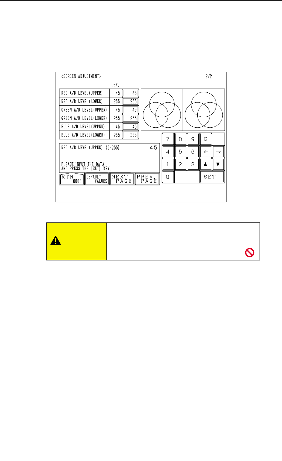
2. RGB (Red-Green-Blue Signal) Adjustment
The produced RGB of the touch screen can be adjusted.
When the [NEXT PAGE] or the [PREV. PAGE] key is pressed at the “SCREEN
ADJUSTMENT” display (Fig. 4E1), the following display appears on the screen.
RED A/D LEVEL (UPPER)
Set the upper limit of the reference voltage for the A/D converter. (R Signal)
The standard value is “45”.
RED A/D LEVEL (LOWER)
Set the lower limit of the reference voltage for the A/D converter. (R signal)
The standard value is “255”.
GREEN A/D LEVEL (UPPER)
Set the upper limit of the reference voltage for the A/D converter. (G Signal)
The standard value is “45”.
GREEN A/D LEVEL (LOWER)
Set the lower limit of the reference voltage for the A/D converter. (G Signal)
The standard value is “255”.
BLUE A/D LEVEL (UPPER)
Set the upper limit of the reference voltage for the A/D converter. (B Signal)
The standard value is “45”.
BLUE A/D LEVEL (LOWER)
Set the lower limit of the reference voltage for the A/D converter. (B Signal)
The standard value is “255”.
[DEFAULT VALUES] Key
When this key is pressed, each parameter is reset to its default.
5-4
2. RGB (Red-Green-Blue Signal) Adjustment
Fig. 4E2
CAUTION
Do not change the parameters unless necessary.
These parameters are factory-adjusted upon ship-
ment of the machine.