4OM-1011-002.pdf - 第287页
0305-001 Tg0860-PM-MM 2. RGB (Red-Green-Blue Signal) Adjustment The produced RGB of the touch screen can be adjusted. When the [NEXT PAGE] or the [PREV. PAGE] key is pressed at the “SCREEN ADJUSTMENT” display (Fig. 4E1),…

0305-001 Tg0860-PM-MM
[DEFAULT VALUES] Key
When this key is pressed, each parameter is reset to its default.
•
When images on the screen appear in bad shape due to the set parameters
and cannot be adjusted, press the [RESET] button. The previous condi-
tion resumes only once. (Undo Function)
When the [RESET] button is pressed again, the original condition (the
condition before “Undo” operation) resumes. (Redo Function)
•
When images on the screen appear in bad shape due to the set parameters
and cannot be adjusted, pressing the [STOP] button sets the default val-
ues in each data box.
5-3
1. SCREEN ADJUSTMENT Display
0305-001 Tg0860-PM-MM
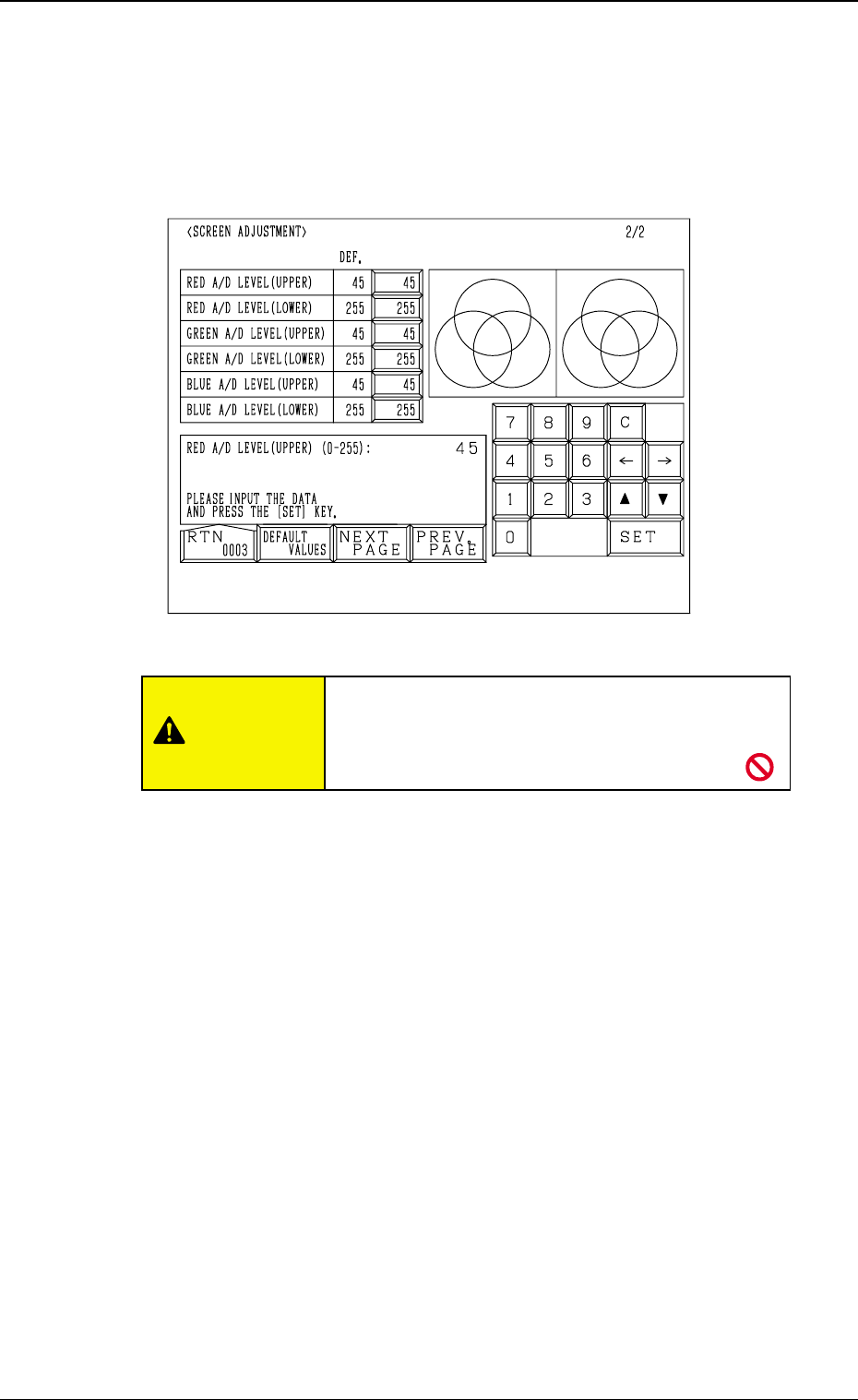
2. RGB (Red-Green-Blue Signal) Adjustment
The produced RGB of the touch screen can be adjusted.
When the [NEXT PAGE] or the [PREV. PAGE] key is pressed at the “SCREEN
ADJUSTMENT” display (Fig. 4E1), the following display appears on the screen.
RED A/D LEVEL (UPPER)
Set the upper limit of the reference voltage for the A/D converter. (R Signal)
The standard value is “45”.
RED A/D LEVEL (LOWER)
Set the lower limit of the reference voltage for the A/D converter. (R signal)
The standard value is “255”.
GREEN A/D LEVEL (UPPER)
Set the upper limit of the reference voltage for the A/D converter. (G Signal)
The standard value is “45”.
GREEN A/D LEVEL (LOWER)
Set the lower limit of the reference voltage for the A/D converter. (G Signal)
The standard value is “255”.
BLUE A/D LEVEL (UPPER)
Set the upper limit of the reference voltage for the A/D converter. (B Signal)
The standard value is “45”.
BLUE A/D LEVEL (LOWER)
Set the lower limit of the reference voltage for the A/D converter. (B Signal)
The standard value is “255”.
[DEFAULT VALUES] Key
When this key is pressed, each parameter is reset to its default.
5-4
2. RGB (Red-Green-Blue Signal) Adjustment
Fig. 4E2
CAUTION
Do not change the parameters unless necessary.
These parameters are factory-adjusted upon ship-
ment of the machine.
0305-001 Tg0860-PM-MM5-5
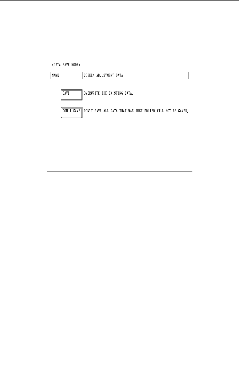
3. DATA SAVE MODE Display
3. DATA SAVE MODE Display
The parameters set for touch screen adjustment can be stored at this display.
When the [RTN] key is pressed at the “SCREEN ADJUSTMENT” display
(Fig. 4E1 or Fig. 4E2), the following display appears on the screen.
[SAVE] Key
When this key is pressed, the parameters changed at the “SCREEN ADJUST-
MENT” display (Figs. 4E1 and 4E2) are saved and then the “MAIN MENU”
display appears on the screen.
[DON’T SAVE] Key
When this key is pressed, the parameters changed at the “SCREEN ADJUST-
MENT” display (Figs. 4E1 and 4E2) are not saved and then the “MAIN MENU”
display appears on the screen.
Fig. 4E3