4OM-1011-002.pdf - 第54页
0305-001 Tg0860-PM-MM 2. SPECIAL SEL. Display When the [SPECIAL SEL.] key is pressed at the “MAIN MENU” display , the following display appears on the screen. *1 [MANAGEMENT DA T A] Key When this key is pressed, the “MAN…
0305-001 Tg0860-PM-MM
DEVICE TEST
(7. in Section 3)
DEVICE CHECK
(8. in Section 3)
HDD/FDD
OPERATION
(9. in Section 3)
(10. in Section 3)
• P.E.C. RECOGNITION TEST
• COMPONENT RECOGNITION TEST
• X/Y BEAM TEST
• INPUT CHECK
• MEMORY CHECK
• MACHINE PROGRAM INFORMA-
TION
• CONVEYOR TIMER ADJUST-
MENT
• FEEDER BASE
• CONVEYOR ADJUSTMENT
• RECOGNITION LIGHTING
• SERVO MOTOR TUNING
• LIGHTING
• SAVE ALL BACKUP DATA
• PATTERN PROGRAM
• OFFSET DATA
• DEVICE DATA
• PLACEMENT HEAD/NOZZLE
DATA
• NOZZLE DATA
• RECALL MESSAGES
UNIT ADJUST-
MENT
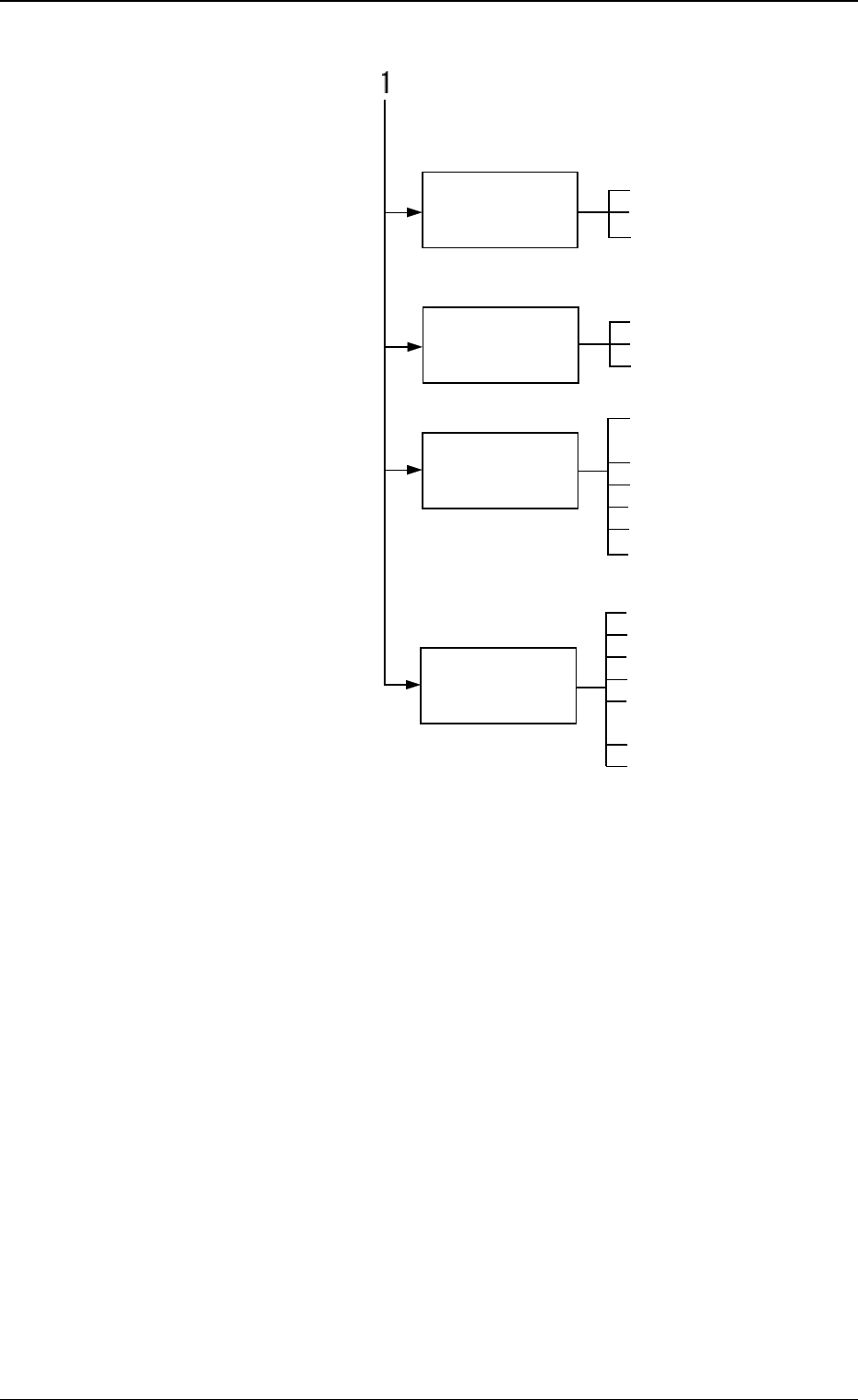
1. Hierarchical Structure of SPECIAL SEL. Displays
3-2
Fig. 4C2
0305-001 Tg0860-PM-MM
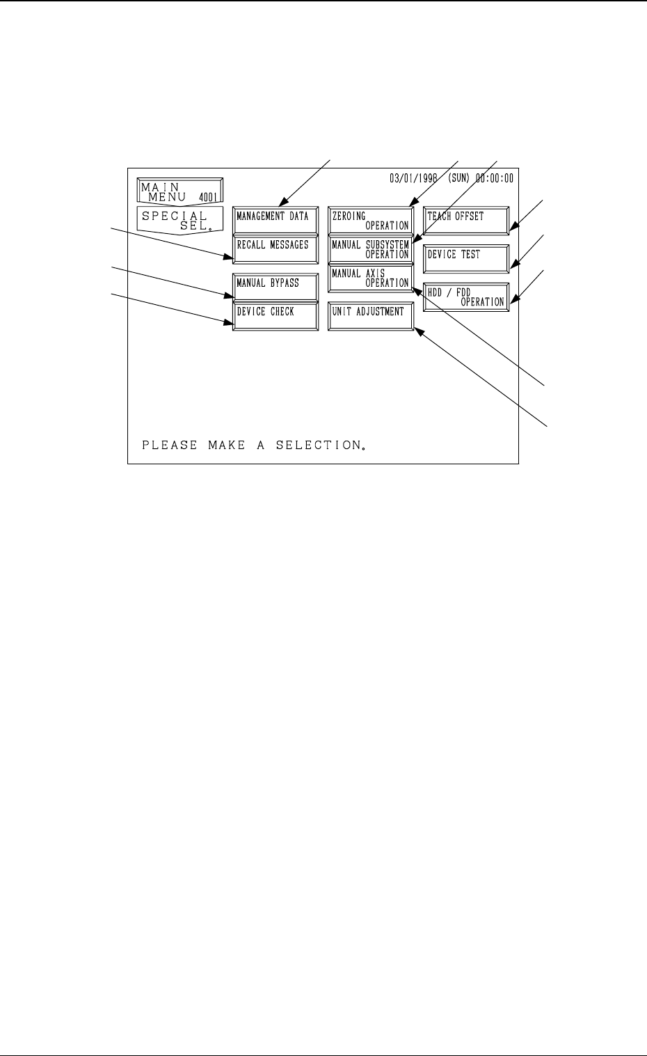
2. SPECIAL SEL. Display
When the [SPECIAL SEL.] key is pressed at the “MAIN MENU” display, the
following display appears on the screen.
*1 [MANAGEMENT DATA] Key
When this key is pressed, the “MANAGEMENT DATA” display appears
on the screen, enabling the selection of menu keys to check management
data such as pattern program management data, time management data,
component handling error rate data, etc.
Nozzle and feeder message rates (deterioration of pick-up rate) can also be
checked.
*2 [RECALL MESSAGES] Key
When this key is pressed, the “RECALL MESSAGES” display appears on
the screen, enabling to recall the machine, pick-up, and recognition errors,
and management information which were called in the past.
Each data is displayed in order of the error occurrence.
*3 [ZEROING OPERATION] Key
When this key is pressed, the “ZEROING OPERATION” display appears
on the screen, enabling the zeroing operation of all or each individual de-
vices.
Refer to “5. ZEROING OPERATION Display of Section 4 in Volume 1”
for details.
*4 [MANUAL SUBSYSTEM OPERATION] Key
When this key is pressed, the “MANUAL SUBSYSTEM OPERATION”
display appears on the screen, enabling the cycle operation of each indi-
vidual devices.
Refer to “6. MANUAL SUBSYSTEM OPERATION Display of Section 4
in Volume 1” for details.
3-3
*3
*4
*1
*7
*11
*8
*5
*10
*2
*6
*9
2. SPECIAL SEL. Display
Fig. 4C3

0305-001 Tg0860-PM-MM
*5 [MANUAL AXIS OPERATION] Key
When this key is pressed, the “MANUAL AXIS OPERATION” display
appears on the screen, enabling the manual axis operation of each indi-
vidual devices.
Refer to “7. MANUAL AXIS OPERATION Display of Section 4 in Vol-
ume 1” for details.
*6 [MANUAL BYPASS] Key
When this key is pressed, the “MANUAL BYPASS” display appears on the
screen, enabling the manual bypass setting of a head or a component recog-
nition camera which is not in good shape or which should not be used.
The bypass setting can also be canceled manually.
*7 [TEACH OFFSET] Key
When this key is pressed, the “TEACH OFFSET” display appears on the
screen, enabling the teaching of various offset data.
After teaching operation, automatically calculated data is saved replacing
the previously saved offset data.
*8 [DEVICE TEST] Key
When this key is pressed, the “DEVICE TEST” display appears on the
screen.
The devices can be activated actually to check operations and functions
when new pattern program or component library data is created.
The [X/Y BEAM TEST], the [P.E.C. RECOG TEST], and the [COMPO-
NENT RECOG TEST] keys are provided.
*9 [DEVICE CHECK] Key
When this key is pressed, the “DEVICE CHECK” display appears on the
screen, enabling the check operation of various sensors’ input ports and the
read/write check operation of CPU boards 1, 2, and 3, the memory board,
and the recognition board.
*10[UNIT ADJUSTMENT] Key
When this key is pressed, the “UNIT ADJUSTMENT” display appears on
the screen, enabling the adjustment of each individual devices.
*11[HDD/FDD OPERATION] Key
When this key is pressed, the “HDD/FDD OPERATION” display appears
on the screen, enabling the load or save operation of the placement data,
using floppy disks.
3-4
2. SPECIAL SEL. Display