4OM-1011-002.pdf - 第76页
0305-001 Tg0860-PM-MM “Saved Data” : Shown are the parameters calculated just before the cur rent parameters. “Current Data” : Shown are the parameters being calculated at present. Examples in Figs. 4C28 and 4C29 : MANAG…
0305-001 Tg0860-PM-MM
3.2.3 Nozzle Bypass Rate
Pick-up rates managed for each nozzle are displayed according to the param-
eters specified at the “AUTO OPERATION SET-UP” display.
When the [NOZZLE BYPASS RATE] key is pressed at the “COMP. HAN-
DLING ERROR RATE DATA” display, the following display appears on the
screen.
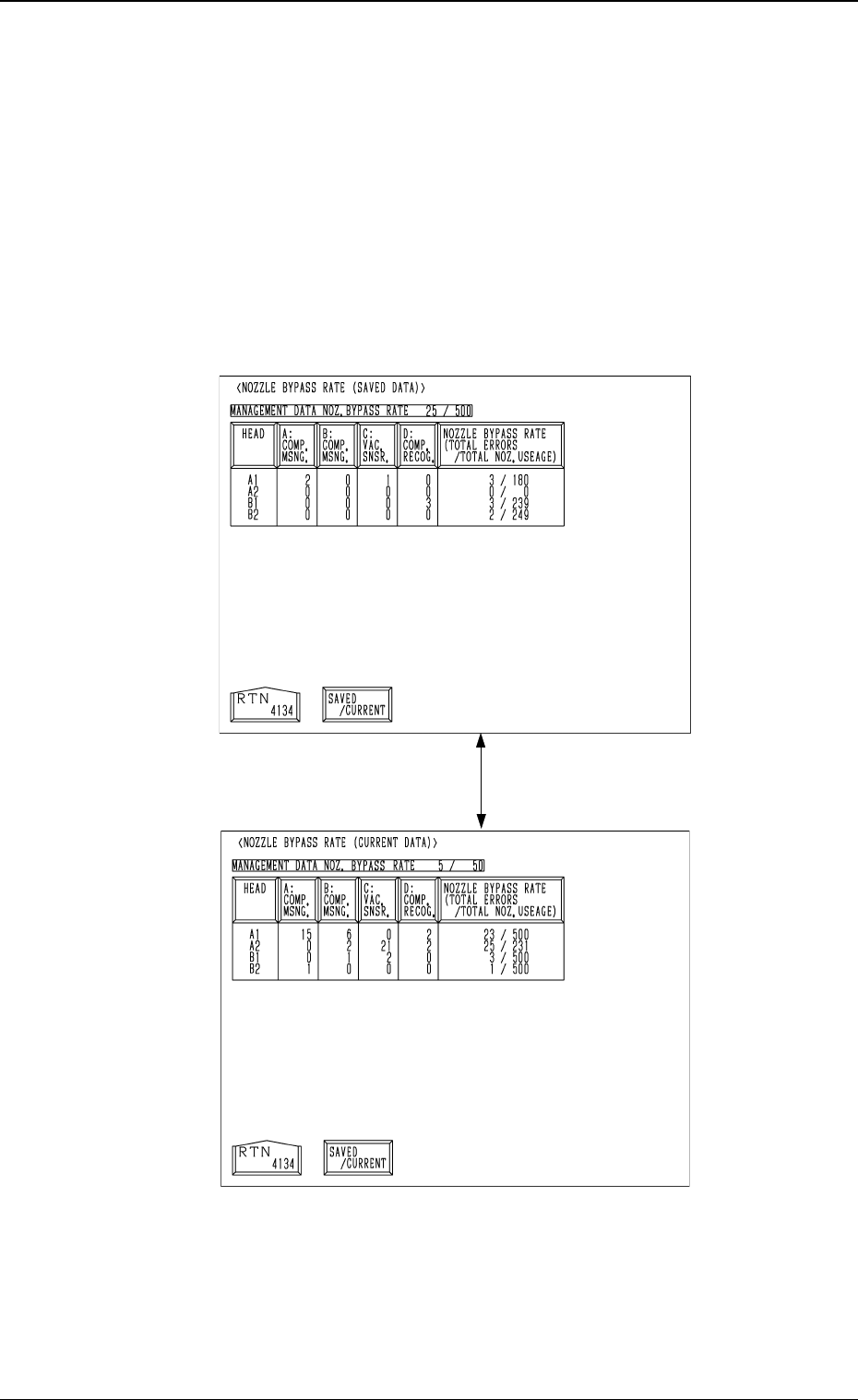
When the [SAVED/CURRENT] key is pressed, the “NOZZLE BYPASS RATE
(SAVED DATA)” display disappears and the “NOZZLE BYPASS RATE (CUR-
RENT DATA)” display appears or vice versa.
SAVED DATA
CURRENT DATA
• When one of the data keys is pressed, the feeder No. with the biggest param-
eter under the selected data key is displayed in the first line and feeder Nos.
having the subsequent (second, third, fourth, ...) biggest parameters follow.
When the [HEAD] key is pressed, head Nos. are arranged in their initial
order.
• Parameters set at the “AUTO OPERATION SET-UP (01/03)” display are
displayed after the label "MANAGEMENT DATA NOZ. BYPASS RATE".
Fig. 4C28
Fig. 4C29
[SAVED/CURRENT] Key
3-24
3.2 Component Handling Error Rate Data

0305-001 Tg0860-PM-MM
“Saved Data” : Shown are the parameters calculated just before the
cur rent parameters.
“Current Data” : Shown are the parameters being calculated at present.
Examples in Figs. 4C28 and 4C29 :
MANAGEMENT DATA NOZ. BYPASS RATE 25/500: Numerator 25 shows
the number of pick-up errors detected before 500 components are picked up.
Denominator 500 shows that 500 components are to be picked up. When 25
pick-up errors are detected, a message appears in the “MGT. INFO.” text box,
indicating that the pick-up rate has deteriorated and the nozzle is automatically
bypassed. When the number of pick-up errors does not reach “25” after 500
components are picked up. XX/XX is reset to “00/00” and counting starts
again.
The “NOZZLE BYPASS RATE (SAVED DATA)” shows the parameters just
before this delimiter.
• When a nozzle is automatically bypassed, the blue head No. related to the
bypassed nozzle turns red at the “NOZZLE BYPASS RATE (SAVED
DATA)” display.
3-25
3.2 Component Handling Error Rate Data
0305-001 Tg0860-PM-MM
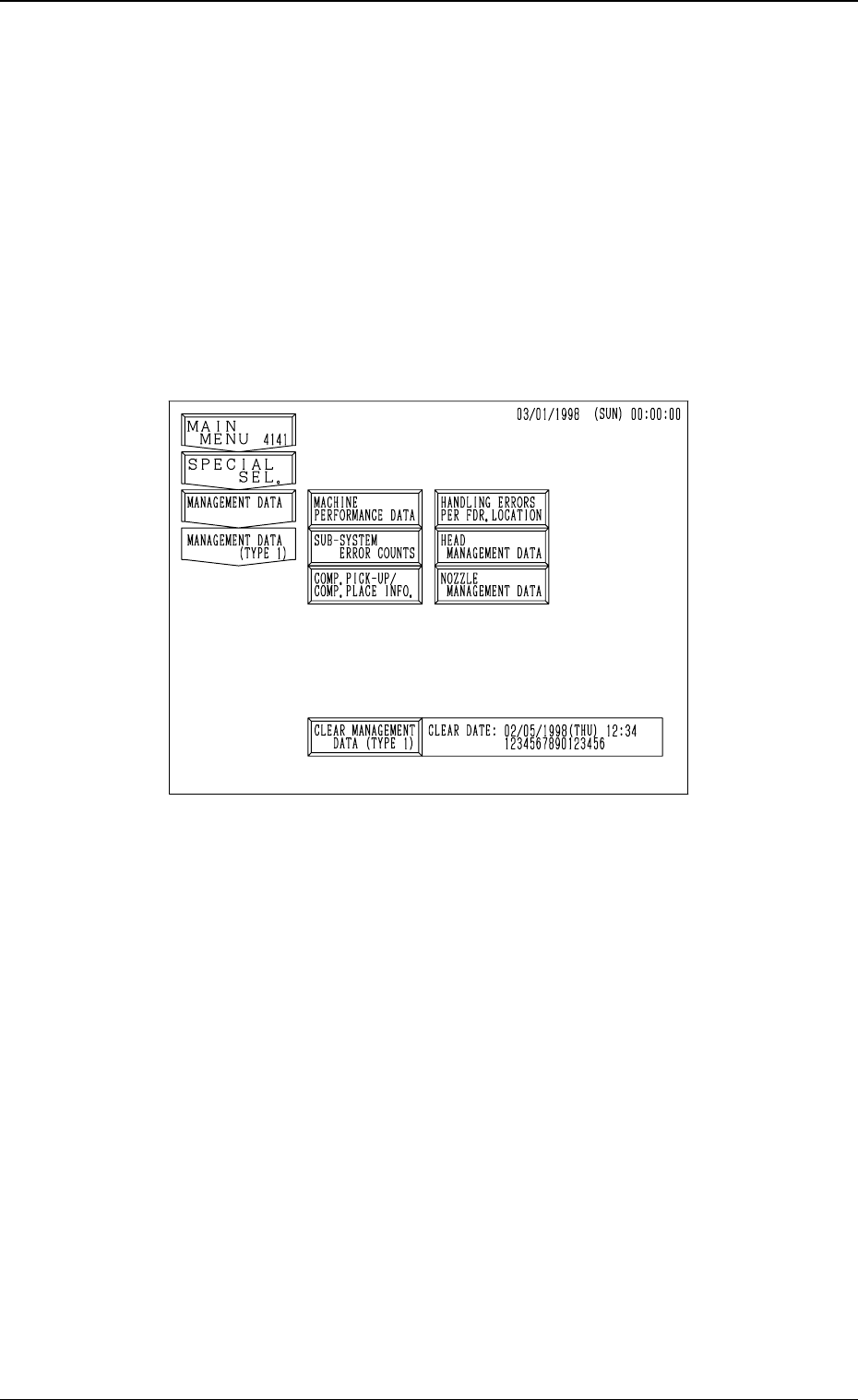
3.3 Management Data (Type 1)
Keys and menus related to production performance of the machine are pro-
vided, enabling the checking of overall performance data.
When the [MANAGEMENT DATA (TYPE 2)] key is pressed at the “MAN-
AGEMENT DATA” display, the “MANAGEMENT DATA (TYPE 2)” dis-
play appears, enabling the checking of almost the same items as those of the
“MANAGEMENT DATA (TYPE 1)” display. Distinguish between manage-
ment spans and check the required items.
When the [MANAGEMENT DATA (TYPE 1)] key is pressed at the “MAN-
AGEMENT DATA” display, the following display appears on the screen.
3-26
3.3 Management Data (Type 1)
Fig. 4C30