4OM-1011-002.pdf - 第95页
0305-001 Tg0860-PM-MM 3-44 6. TEACH OFFSET Display *2 [COMPONENT RECOG CAMERA MAGNIFICA TION (STEP-2)] Key When this key is pressed, the "COMP . RECOG. CAMERA MAG. (STEP- 2)" display appears on the screen, enab…
0305-001 Tg0860-PM-MM
6. TEACH OFFSET Display
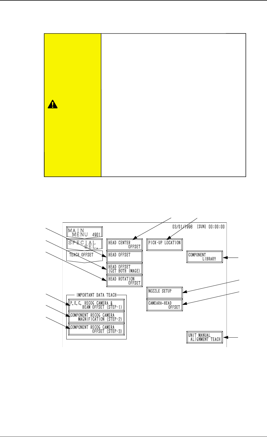
When the [TEACH OFFSET] key is pressed at the “SPECIAL SEL.” display,
the following display appears on the screen.
Note: The -marked function is optional.
*1 [P.E.C. RECOG CAMERA & BEAM OFFSET (STEP-1)] Key
When this key is pressed, the “P.E.C. RECOG CAMERA & BEAM OFF-
SET (STEP-1)” display appears on the screen, enabling to teach the X/Y
beam and P.E.C. camera offset data.
Note: A special jig P.C.B. (option) is required.
The parameters are factory-set at shipment. It is not necessary to
teach these parameters.
*1
*2
*3
*4
*10
*11
*8
*9
3-43
6. TEACH OFFSET Display
Fig. 4C54
*5
*6
*7
CAUTION
•The accuracy of component placement is affected
by the teaching operations. Only our service per-
sonnel or a trained one shall perform teaching op-
erations.
•Some operations require special jigs (option).
Consult our sales personnel before performing
any teaching operations.
•Follow the teaching procedures in the specified
order. Otherwide, some trouble (such as inaccu-
rate component placement, frequent mechanical
errors, etc.) will arise.
•Before performing the teaching operation, check
that the component recognition offset jig, the jig
location, and the back light stage (teaching plate)
are not nicked nor stained.
Refer to
“6. Monthly Maintenance of Section 1”
for details.

0305-001 Tg0860-PM-MM
3-44
6. TEACH OFFSET Display
*2 [COMPONENT RECOG CAMERA MAGNIFICATION (STEP-2)] Key
When this key is pressed, the "COMP. RECOG. CAMERA MAG. (STEP-
2)" display appears on the screen, enabling to teach the magnification of the
component recognition camera.
Note: A special jig (option) is required. The parameters are factory-set at
shipment. It is not necessary to teach these parameters.
*3 [COMPONENT RECOG CAMERA OFFSET (STEP-3)] Key
When this key is pressed, the "COMP. RCG. CAMR. OFST. (STEP3)"
display appears on the screen, enabling to teach the component recognition
camera offset data.
*4 [HEAD CENTER OFFSET] Key
When this key is pressed, the "HEAD CENTER OFFSET" display appears
on the screen, enabling to teach the head center offset data.
*5 [HEAD OFFSET] Key
When this key is pressed, the "HEAD OFFSET" display appears on the
screen, enabling to teach the head offset data.
*6 [HEAD OFFSET (GET BOTH IMAGE)] Key
When this key is pressed, the "HEAD OFFSET (GET BOTH IMAGE)"
display appears on the screen, enabling the teaching operation of the head
position offset for the simultaneous image capture function.
*7 [HEAD ROTATION OFFSET] Key
When this key is pressed, the "HEAD ROTATION OFFSET" display ap-
pears on the screen, enabling to teach the head rotation offset data.
Note: A special jig NOZZLE (option) is required. The parameters are
factory-set at shipment. It is not necessary to teach these param-
eters.
*8 [UNIT MANUAL ALIGNMENT TEACH] Key
When this key is pressed, the "UNIT MANUAL ALIGNMENT TEACH"
display appears on the screen, enabling to teach the offset data for the units
such as the feeder, the nozzle stocker, etc.
*9 [PICK-UP LOCATION] Key
When this key is pressed, the "PICK-UP LOCATION" display appears on
the screen, enabling to teach the component pick-up location through manual
alignment operation.
*10 [NOZZLE SETUP] Key
When this key is pressed, the “NOZZLE SETUP” display appears
on the screen, enabling to setup the nozzle.
*11 [CAMERA-HEAD OFFSET] Key
When this key is pressed, the “CAMERA HEAD OFFSET” display
appears on the screen, enabling to teach camera-head offset.
0305-001 Tg0860-PM-MM
Notes: (a) When “P.E.C. Recognition Camera & Beam Offset (Step 1)” must
be taken, perform the teaching operation of [Teaching Plate Off-
set] before [Component Recognition Camera Offset (Step 3)].
In this case, also perform the following teaching operation after
teaching of “Head Offset (Get Both Image)” is complete.
“Nozzle Stoker Offset”
“Traverse Offset (Option)”
(b) After the head section is changed, perform the teaching operation
on the lighting at the “LIGHTING” display before “Component
Recognition Camera Magnification (Step 2)”. (Hierarchical Se-
quence: “SPECIAL SEL.” Display → “UNIT ADJUSTMENT”
Display → “LIGHTING” Display)
3-45
6. TEACH OFFSET Display
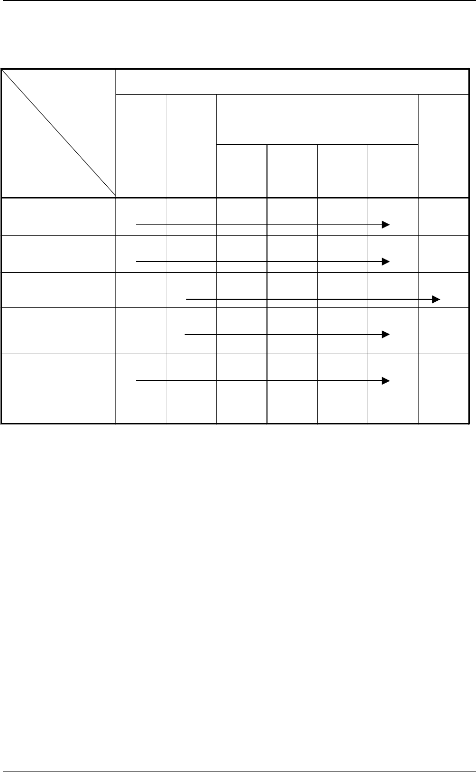
Order of Teaching Operations: The {-marked items should be implemented
sequentially from the left to the right one.
Camera head offset teaching available
Teaching Items
Operational Items
P. E . C .
Recognition
Camera &
Beam Offset
(Step 1)
Component
Recognition
Camera
Magnification
(Step 2)
Component
Recognition
Camera
Offset
(Step 3)
Head
Center
Offset
Head
Offset
Head
Offset
(Get Both
Image)
Head
Rotation
Offset
P.C.B. Recognition
Camera Change
{
*1
− {
*2
{
*3
{
*4
{
*5
−
Motor for Readjustment of
Beam Origin, Slide Origin
Sensor Change, Others
{
*1
− {
*2
{
*3
{
*4
{
*5
−
Change of Head Section
Note: (b)
− {
*1
{
*2
{
*3
{
*4
{
*5
{
*6
Component Recognition
Camera Change
(View Change, etc.)
{
*1
{
*2
{
*3
{
*4
{
*5
−
Maintenance of P.C.B.
Positioning Section
• Stopper Change
• Transfer Section including
Fixed Chute
Unit Change
{
*1
− {
*2
{
*3
{
*4
{
*5
−
Table 4C3 List of Operational and Teaching Items
(items which require the offset teaching)