Oxford-100-Manual.pdf - 第10页
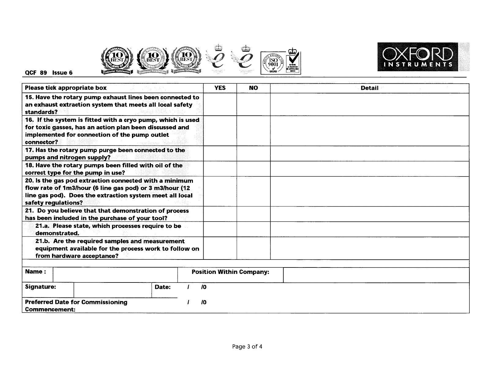
QCF 89 Issue 6 Please tick appropriate box 15. Have the rotary pump exhaust lines been. connected to an exhaust extraction system that meets all local safety standards? 16. If the system is fitted with a cryo pump, which…
QCF
89
Issue 6
Please return the completed form
to
your nearest Oxford Instruments
Support Office, detailed below:
USA & Canada
Oxford
Instruments America Inc
Plasma Technology Support Manager
130A Baker Avenue Extension
Concord
MA
01742
Tel: (800) 447 4717
Fax:
(978) 3698287
Email: CSG@ma.oxinst.com
DE, NE,
B,
SE,
FI,DK
Oxford
Instruments GmbH
Plasma Technology
Postfach 4509
65035 Wiesbaden
Germany
Tel: +496122937161
Fax:
+496122937175
Email: Plasma@oxford.de
Eastern Territories
Oxford
Instruments Pte. Ltd
Raymond
Wong
371
Beach Road
#02-07 Keypoint
Singapore 199597
Tel:
+6563376848
Fax:
+65
6337 6286
Email: Raymond.Wong@oxford-instruments.com.sg
Page 4
of
4
U.K.
and
all
Other
Territories
Oxford
Instruments Plasma
Technology
Global Support
Manager
North
End
Yatton,
Nr Bristol
BS494AP.
U.K.
Tel:
+441934837070
Fax:
+44 1934 837071
Email: Support.PT@oxinst.co.uk
QCF
89
Issue 6
Please
tick
appropriate
box
15.
Have
the
rotary
pump
exhaust
lines
been.
connected
to
an
exhaust
extraction
system
that
meets
all
local
safety
standards?
16.
If
the
system
is
fitted
with
a
cryo
pump,
which
is
used
for
toxic
gasses,
has
an
action
plan
been
discussed
and
impl,me.,t'd
for
connection
of
the
pump
outlet
connector?
17.
Has
the
rotary
pump
purge
been
connected
to
the
DumDS
and
nitroaen
SUDDly?
18.
Have
the
rotary
pumps
been
filled
with
oil
of
the
correct
tYDe
for
the
DumD
in
use?
20.
Is
the
gas
pod
extraction
connected
with
a
minimum
flow
rate
of
1m3/hour
(6
line
gas
pod)
or
3
m3/hour
(12
line
gas
pod).
Does
the
extraction
system
meet
all
local
safety
reaulations?
21.
Do
you
believe
that
that
demonstration
of
process
has
been
included
in
the
Durchase
of
your
tool?
21.~.>Please
state,
which
processes
require
to
be
demonstrated.
21.b.
Are
the
required
samples
and
measurement
equipment
available
for
the
process
work
to
follow
on
from
hardware
acceDtance?
YES
NO
Detail
Name:
1
Signature:
1
1
Date:
1
Position
Within
Company:
/0
1
Preferred
Date
for
Commissioning
Commencement:
/0
Page 3
of
4
QCF
89
Issue 6
C9rnpressed
Air
Inlet
Pressure
I
Please
tick
appropriate
box
7.
Has
AC
power
been
connectEKi
to
the
system?
Measure
the
voltages
between
each
Dhase
and
neutral.
8.
Has
compressed
air
been
connected
to
the
system?
Inlet
pressure
must
be
6
Bar
(90PSI).
N()te
Pressure.
YES
I NO
Phase 1
to
T
Neutral
Detail
Phase 2
to
Neutral
Phase 3
to
Neutral
9.
Has
cooling
water
been
connected
to
the
system?
Differential
pressure
between
inlet
and
outlet
must
be
3 • 4
Bar
(45
- 60PSI).
Water
supply
should
be
connected
to
each
inlet/outlet
on
the
system
in
Darallel
and
not
series.
Note
Inlet
and
Outlet
Pressure.
Inlet
Water
Pressure
Outlet
Water
Pressure
1~.~as
N2
vent
bee~conne~~ed.
to
th~~~$tem?
..
Inlet
must
be
able
maintain
a
pressure.()f3
Bar
(45psig).
Note
Pressure.
Vent
Nitrogel1lnlet
Pressure
11.
Has
N2purge.been
connected
to~"'e
system?/Inlet
mustl).e
able
maintain
a
pressure
of
3
Bar
(45psig).
Note
Pressure.
f'urge
Nitrogen
Inlet
Pressure.
12.
If
the
system
is
configured
with
cryogenic
cooling,
is
an
LN2
Dewar,
filled
with
LN2
available?
Is
the
Dewar
connected
to
the
system
via
3/8"
Swagelock
connections
and
is
the
pipe
work
adequately
insulated
to
Drevent
a
safetv
hazard?
Is
the
pipe
work
adequately
insulated
to
prevent
a
safety
hazard?
13
••
I~~e
all
of
th~~as
pod
connections
been
made
t()the
appropriate
aas
SUDDly
or
system
connection.
Have
they
been
leak
checked?
Leak
Rate
Heated
?
Inlet
Pressure
Name
of
Gas
Gas 7
Leak
Rate
Heated
?
Inlet
Pressure
Name
of
Gas
14.
AIIJ)f'(:)cess gasses
shoulc:f/beavailabl~f()r
the
systell1
commissioning.
Plea~everifythat
eachg~s,
as
it
is
laid
out
in
the
gas
pod
is
connected,
avail.ablefor
process
and
that
the
gas
line
has
been
leak
checked.
IGas 1·1 I I I I I I I I I
Please
record
the
leak
rate
for
each
gas
line.
If
there
is
no
line
fitted
please
enter
N/A.
Process
gas
inlet
pressure
should
be
set
at
3
Bar
(45psig).
Minimum
acceptable
inlet
pressure:
2
Bar
(30psig).
Maximum
acceptable
inlet
pressure:
5
Bar
(75psig).
If
the
gas
line
is
to
be
used
for
BCI3, SiCI4
or
TEOS,
has
the
gas
line
been
wrapped
with
trace
heater
wire
and
insulated?
Failure
to
do
so
could
result
in
condensation
of
the
gas,
within
the
line
during
processing.
Gas 2
Gas 3
Gas 4
Gas 5
Gas 6
Gas 8
Gas 9
Gas
10
Gas 11
Gas
12
Page 2
of
4