Oxford-100-Manual.pdf - 第115页
System Manual Oxford Instruments Plasma Technology PlasmalabSystem 1 00 5.8.8.1 f) Process chamber rotary vane/dry pump. g) Automatic load lock transfer arm (click red dot to insert/withdraw arm). h) Automatic load lock …
PiasmaiabSystem100
Oxford
Instruments
Plasma Technology
System Manual
5.8.8
Service
mode
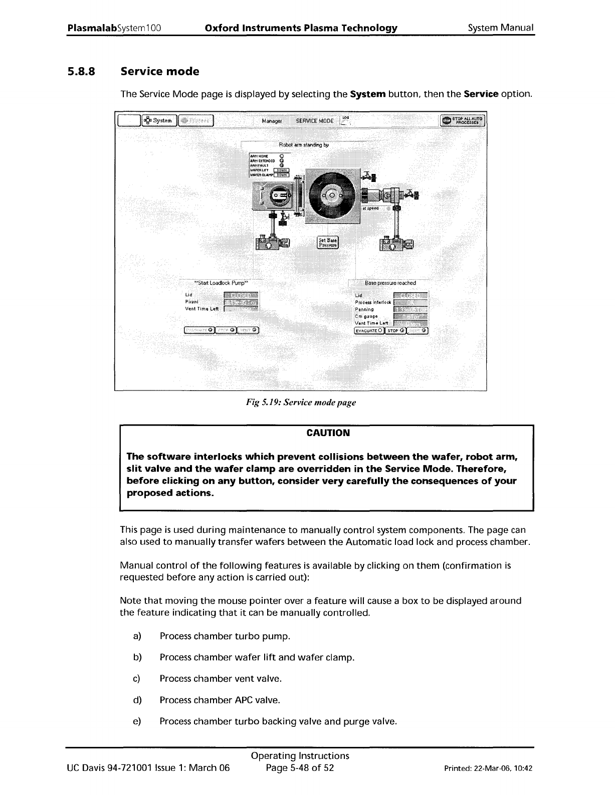
The Service
Mode
page
is
displayed
by
selecting
the
System
button,
then
the
Service
option.
Fig 5.19: Service modepage
CAUTION
The
software
interlocks
which
prevent
collisions
between
the
wafer,
robot
arm,
slit
valve
and
the
wafer
clamp
are
overridden
in
the
Service
Mode.
Therefore,
before
clicking
on
any
button,
consider
very
carefully
the
consequences
of
your
proposed
actions.
This page
is
used
during
maintenance
to
manually
control
system components. The page can
also used
to
manually
transfer
wafers
between
the
Automatic
load lock and process chamber.
Manual
control
of
the
following
features
is
available by clicking on
them
(confirmation
is
requested
before
any
action
is
carried out):
Note
that
moving
the
mouse
pointer
over a
feature
will
cause a box
to
be displayed
around
the
feature
indicating
that
it
can be
manually
controlled.
a)
Process
chamber
turbo
pump.
b) Process chamber
wafer
lift
and
wafer
clamp.
c)
Process
chamber
vent
valve.
d) Process chamber APe valve.
e)
Process
chamber
turbo
backing valve and
purge
valve.
UC
Davis 94-721001
Issue
1:
March 06
Operating
Instructions
Page 5-48
of
52
Printed: 22-Mar-06, 10:42
System
Manual
Oxford Instruments Plasma Technology
PlasmalabSystem1
00
5.8.8.1
f) Process chamber
rotary
vane/dry pump.
g)
Automatic
load lock
transfer
arm (click red
dot
to
insert/withdraw
arm).
h)
Automatic
load lock isolating valve.
i)
Automatic
load lock
vent
valve.
j)
Automatic
load lock
drylrotary
vane pump.
k) Slit valve.
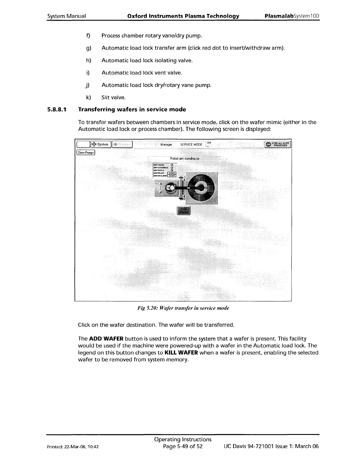
Transferring
wafers
in service
mode
To
transfer
wafers
between
chambers
in
service mode, click
on
the
wafer
mimic
(either
in
the
Automatic
load lock
or
process chamber). The
following
screen
is
displayed:
Fig 5.20: Wafer transfer in service mode
Click on
the
wafer
destination. The
wafer
will
be transferred.
The
ADD
WAFER
button
is
used
to
inform
the
system
that
a
wafer
is
present. This
facility
would
be used
if
the
machine
were
powered-up
with
a
wafer
in
the
Automatic
load lock. The
legend on this
button
changes
to
KILL WAFER
when
a
wafer
is
present,
enabling
the
selected
wafer
to
be removed
from
system memory.
Printed: 22-Mar-06. 10:42
Operating
Instructions
Page 5-49
of
52
UC
Davis 94-721001
Issue
1:
March 06
PlasmalabSystem100
Oxford
Instruments Plasma Technology
System Manual
The page provides
the
following
facilities:
Show
Pumps
button
Message
field
Add/Kill
Wafer
button
Wafer
transfer
path
Displays
the
Pump
Control
page
Displays status messages
about
the
wafer
transfer.
The
ADD
WAFER
button
is
used
to
inform
the
system
that
a
wafer
is
present. This
facility
would
be used
if
the
machine
were
powered-up
with
a
wafer
in
the
Automatic
load lock. The legend
on
this
button
changes
to
KILL WAFER
when
a
wafer
is
present.
enabling
the
selected
wafer
to
be
removed
from
system memory.
Displayed
when
the
wafer
mimic has been clicked.
An
arrow
indicates
the
direction
of
the
possible transfer. Clicking on
the
destination
will
cause
the
transfer
to
be
carried
out.
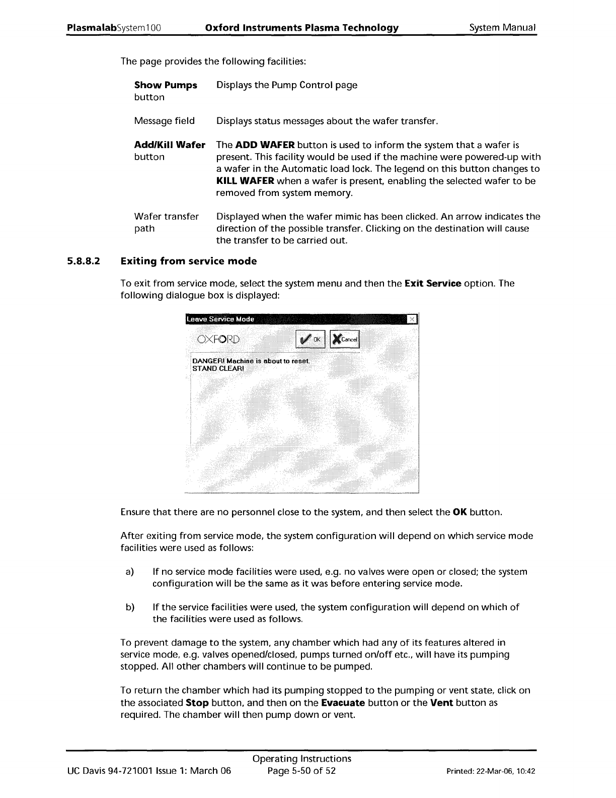
5.8.8.2
Exiting
from
service
mode
To
exit
from
service mode, select
the
system
menu
and
then
the
Exit Service
option.
The
following
dialogue
box
is
displayed:
Ensure
that
there
are
no
personnel close
to
the
system, and
then
select
the
OK
button.
After
exiting
from
service mode,
the
system
configuration
will
depend
on
which
service
mode
facilities
were
used
as
follows:
a)
If
no
service
mode
facilities
were
used, e.g.
no
valves
were
open
or
closed;
the
system
configuration
will
be
the
same
as
it
was
before
entering
service mode.
b)
If
the
service facilities
were
used,
the
system
configuration
will
depend on
which
of
the
facilities
were
used
as
follows.
To
prevent
damage
to
the
system, any chamber
which
had any
of
its features altered in
service mode, e.g. valves opened/closed, pumps
turned
on/off
etc.,
will
have its
pumping
stopped.
All
other
chambers
will
continue
to
be pumped.
To
return
the
chamber
which
had its
pumping
stopped
to
the
pumping
or
vent
state, click on
the
associated
Stop
button,
and
then
on
the
Evacuate
button
or
the
Vent
button
as
required. The chamber
will
then
pump
down
or
vent.
UC
Davis 94-721001
Issue
1:
March 06
Operating
Instructions
Page 5-50
of
52
Printed: 22-Mar-06, 10:42