Oxford-100-Manual.pdf - 第12页
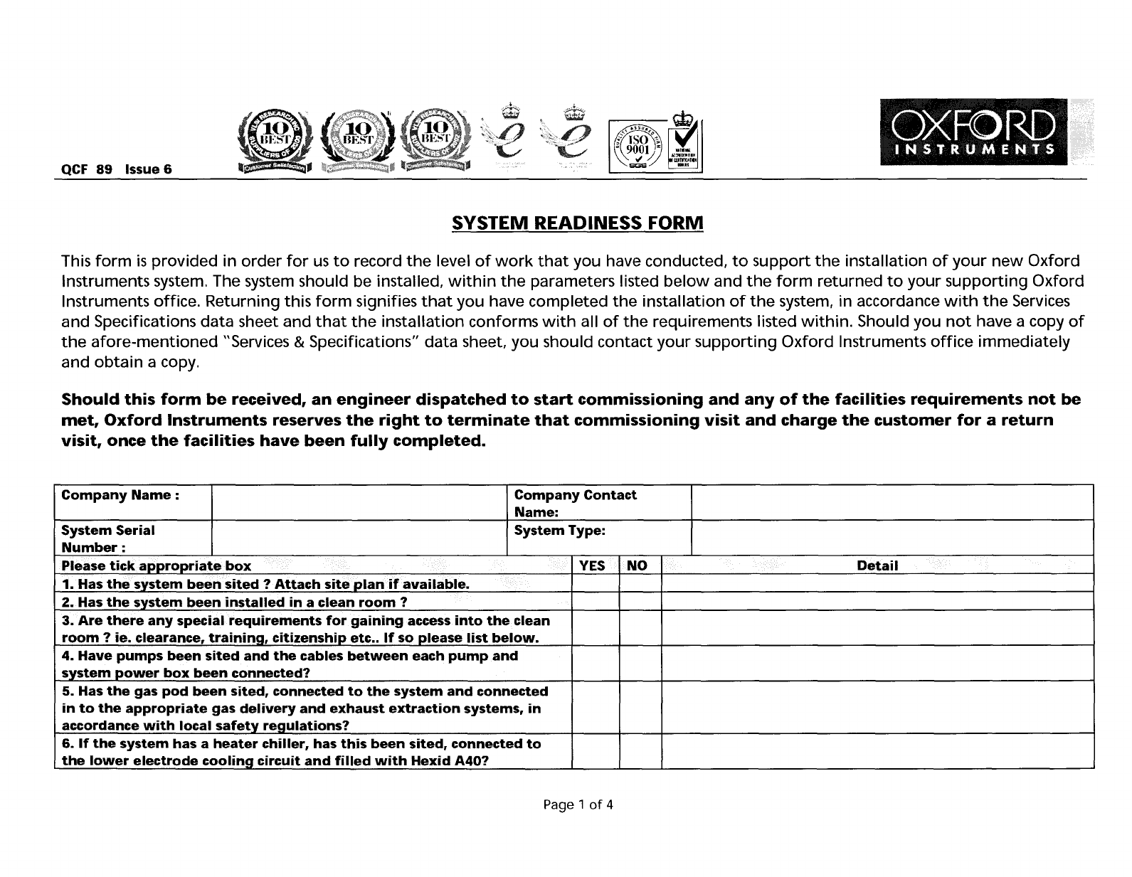
QCF 89 Issue 6 SYSTEM READINESS FORM This form is provided in order for us to record the level of work that you have conducted, to support the installation of your new Oxford Instruments system. The system should be inst…
QCF
89
Issue 6
C9rnpressed
Air
Inlet
Pressure
I
Please
tick
appropriate
box
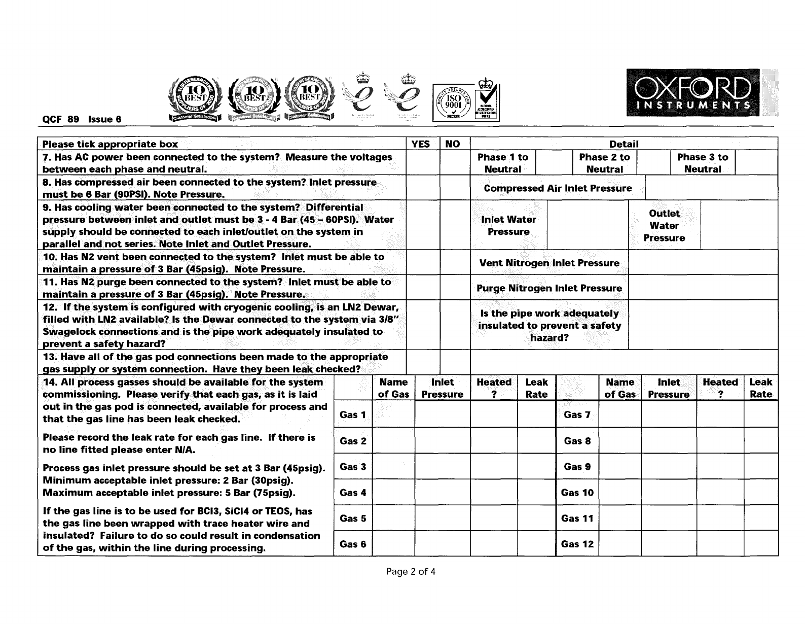
7.
Has
AC
power
been
connectEKi
to
the
system?
Measure
the
voltages
between
each
Dhase
and
neutral.
8.
Has
compressed
air
been
connected
to
the
system?
Inlet
pressure
must
be
6
Bar
(90PSI).
N()te
Pressure.
YES
I NO
Phase 1
to
T
Neutral
Detail
Phase 2
to
Neutral
Phase 3
to
Neutral
9.
Has
cooling
water
been
connected
to
the
system?
Differential
pressure
between
inlet
and
outlet
must
be
3 • 4
Bar
(45
- 60PSI).
Water
supply
should
be
connected
to
each
inlet/outlet
on
the
system
in
Darallel
and
not
series.
Note
Inlet
and
Outlet
Pressure.
Inlet
Water
Pressure
Outlet
Water
Pressure
1~.~as
N2
vent
bee~conne~~ed.
to
th~~~$tem?
..
Inlet
must
be
able
maintain
a
pressure.()f3
Bar
(45psig).
Note
Pressure.
Vent
Nitrogel1lnlet
Pressure
11.
Has
N2purge.been
connected
to~"'e
system?/Inlet
mustl).e
able
maintain
a
pressure
of
3
Bar
(45psig).
Note
Pressure.
f'urge
Nitrogen
Inlet
Pressure.
12.
If
the
system
is
configured
with
cryogenic
cooling,
is
an
LN2
Dewar,
filled
with
LN2
available?
Is
the
Dewar
connected
to
the
system
via
3/8"
Swagelock
connections
and
is
the
pipe
work
adequately
insulated
to
Drevent
a
safetv
hazard?
Is
the
pipe
work
adequately
insulated
to
prevent
a
safety
hazard?
13
••
I~~e
all
of
th~~as
pod
connections
been
made
t()the
appropriate
aas
SUDDly
or
system
connection.
Have
they
been
leak
checked?
Leak
Rate
Heated
?
Inlet
Pressure
Name
of
Gas
Gas 7
Leak
Rate
Heated
?
Inlet
Pressure
Name
of
Gas
14.
AIIJ)f'(:)cess gasses
shoulc:f/beavailabl~f()r
the
systell1
commissioning.
Plea~everifythat
eachg~s,
as
it
is
laid
out
in
the
gas
pod
is
connected,
avail.ablefor
process
and
that
the
gas
line
has
been
leak
checked.
IGas 1·1 I I I I I I I I I
Please
record
the
leak
rate
for
each
gas
line.
If
there
is
no
line
fitted
please
enter
N/A.
Process
gas
inlet
pressure
should
be
set
at
3
Bar
(45psig).
Minimum
acceptable
inlet
pressure:
2
Bar
(30psig).
Maximum
acceptable
inlet
pressure:
5
Bar
(75psig).
If
the
gas
line
is
to
be
used
for
BCI3, SiCI4
or
TEOS,
has
the
gas
line
been
wrapped
with
trace
heater
wire
and
insulated?
Failure
to
do
so
could
result
in
condensation
of
the
gas,
within
the
line
during
processing.
Gas 2
Gas 3
Gas 4
Gas 5
Gas 6
Gas 8
Gas 9
Gas
10
Gas 11
Gas
12
Page 2
of
4
QCF
89
Issue
6
SYSTEM READINESS FORM
This
form
is
provided in order
for
us
to
record
the
level
of
work
that
you have conducted,
to
support
the
installation
of
your
new
Oxford
Instruments system. The system should be installed,
within
the
parameters listed
below
and
the
form
returned
to
your
supporting
Oxford
Instruments office. Returning this
form
signifies
that
you have completed
the
installation
of
the
system, in accordance
with
the
Services
and Specifications data sheet and
that
the
installation conforms
with
all
of
the
requirements listed
within.
Should you
not
have a copy
of
the
afore-mentioned
"Services & Specifications" data sheet, you should contact
your
supporting
Oxford Instruments
office
immediately
and
obtain
a copy.
Should
this
form
be
received,
an
engineer
dispatched
to
start
commissioning
and
any
of
the
facilities
requirements
not
be
met,
Oxford
Instruments
reserves
the
right
to
terminate
that
commissioning
visit
and
charge
the
customer
for
a
return
visit,
once
the
facilities
have
been
fully
completed.
Company
Name:
Company
Contact
Name:
System
Serial
System
Type:
Number:
Please
tick
appropriate
box
YES
NO
Detail
1. Has
the
system
been
sited?
Attach
site
plan
if
available.
2.
Has
the
system
been
installed
in a
clean
room?
3.
Are
there
any
special
requirements
for
gaining
access
into
the
clean
room?
ie.
clearance,
trainina,
citizenship
etc
.. If
so
please
list
below.
4.
Have
pumps
been
sited
and
the
cables
between
each
pump
and
system
power
box
been
connected?
5. Has
the
gas
pod
been
sited,
connected
to
the
system
and
connected
in
to
the
appropriate
gas
delivery
and
exhaust
extraction
systems,
in
accordance
with
local
safety
regulations?
6. If
the
system
has
a
heater
chiller,
has
this
been
sited,
connected
to
the
lower
electrode
cooling
circuit
and
filled
with
Hexid A40?
Page 1
of
4
Health and Safety
Oxford
Instruments
Plasma
Technology
Plasma
lab
and
lonfab
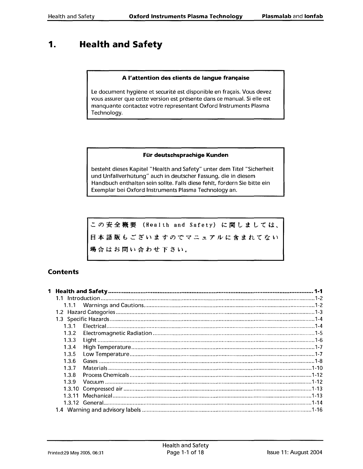
1.
Health
and
Safety
A
I'attention
des
clients
de
langue
fran~aise
Le
document
hygiene
et
securite est disponible en fracais. Vous devez
vous assurer
que
cette
version est presente dans
ce
manual.
Si
elle est
manquante
contactez
votre
representant
Oxford
Instruments Plasma
Technology.
Fur
deutschsprachige
Kunden
besteht dieses Kapitel
"Health
and Safety"
unter
dem Titel "Sicherheit
und
UnfaliverhUtung"
auch
in
deutscher Fassung, die in diesem
Handbuch
enthalten
sein sollte. Falls diese
fehlt,
fordern
Sie
bitte
ein
Exemplar bei
Oxford
Instruments Plasma Technology an.
':'(J)~~I!t"
(Health
and
Safety)
':AL;i
L"(t;t,
Ef
*
ij
Iiti
b
::::
<'r
~
\
;i
T 11)
"c"
"7
.:::.
.:7.
7
Iv
t:
~
;:
it
"(
>j:
~
\
ili;t±:Bra1~\i;.b'ttr~
p.
Contents
1
Health
and
Safety
1·1
1.1
Introduction
1-2
1.1.1 Warnings and Cautions 1-2
1.2 Hazard Categories 1-3
1.3 Specific Hazards 1-4
1.3.1 Electrical 1-4
1.3.2 Electromagnetic Radiation 1-5
1.3.3
Light
1-6
1.3.4
High
Temperature
1-7
1.3.5
Low
Temperature
1-7
1.3.6
Gases
1-8
1.3.7 Materials 1-10
1.3.8 Process Chemicals 1-12
1.3.9 Vacuum 1-12
1.3.10 Compressed air 1-13
1.3.11 Mechanical 1-13
1.3.12 General. 1-14
1.4
Warning
and advisory labels 1-16
Printed:29 May 2005, 06:31
Health and Safety
Page
1-1
of
18
Issue
11:
August
2004