Oxford-100-Manual.pdf - 第153页
System Manual Oxford Instruments Plasma Technology Plasma lab (c) For processes which deposit a combination of etched material and mask layer, e.g. GaAs and sputtered photoresist during GaAs 'via hole etching' …
Plasma
lab
Oxford
Instruments
Plasma
Technology
System
Manual
3.2.5
Arcing I
pitting
Arcing
around
the
showerhead could be related
to:
(a)
Contamination
of
the
showerhead / chamber walls (e.g.
insulating/polymer
coating,
backstreaming
of
pump
oil
or
excessive use
of
vacuum grease
on
o-rings).
(b) A
fault
in
the
matching
unit,
more
specifically
the
DC
bias measurement circuit. Running
at
high
bias
for
extended periods can
potentially
cause damage
to
the
DC
bias measurement circuit
which
can lead
to
a change in electrode performance and increased plasma
potential
causing sparking
on
grounded
walls.
DC
bias readings are also
greatly
reduced by this
fault.
It
may be
worth
manually
scrubbing
the
showerhead and
then
trying
again.
If
you
are still seeing sparking
then
it
is
worth
investigating
the
matching
unit.
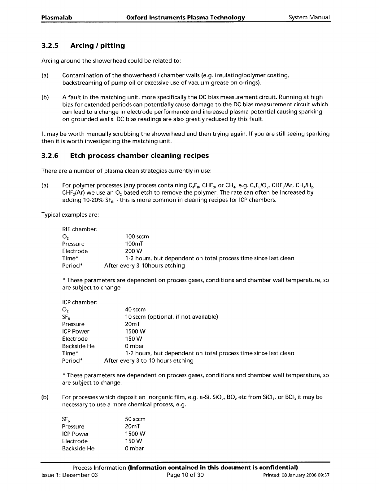
3.2.6
Etch process
chamber
cleaning recipes
There are a
number
of
plasma clean strategies
currently
in
use:
(a)
For
polymer
processes (any process
containing
C
4
F
a
,
CHF
3
,
or
CH
4
,
e.g. C
4
F
a
/0
2
,
CHFiAr,
CHiH
2
,
CHFiAr)
we
use an O
2
based etch
to
remove
the
polymer. The
rate
can
often
be increased by
adding
10-20%
SF
6
, -
this
is
more
common
in cleaning recipes
for
ICP
chambers.
Typical examples are:
RIE
chamber:
O
2
Pressure
Electrode
Time*
Period*
100
sccm
100mT
200W
1-2 hours,
but
dependent
on
total
process
time
since last clean
After
every 3-10hours
etching
* These parameters are
dependent
on
process
gases,
conditions and chamber
wall
temperature,
so
are subject
to
change
ICP
chamber:
O
2
SF
6
Pressure
ICP
Power
Electrode
Backside He
Time*
Period*
40
sccm
10
sccm
(optional,
if
not
available)
20mT
1500W
150W
o
mbar
1-2 hours,
but
dependent
on
total
process
time
since last clean
After
every 3
to
10 hours
etching
* These parameters are
dependent
on process
gases,
conditions
and chamber
wall
temperature,
so
are subject
to
change.
(b) For processes
which
deposit an inorganic
film,
e.g. a-Si,
Si0
2
,
BOx
etc
from
SiCI
4
,
or
BCI
3
it
may be
necessary
to
use a
more
chemical process, e.g.:
SF
6
Pressure
ICP
Power
Electrode
Backside He
50
sccm
20mT
1500W
150W
o
mbar
Process
Information
(Information
contained
in
this
document
is
confidential)
Issue
1:
December 03 Page 10
of
30 Printed: 08 January 2006 09:37
System
Manual
Oxford
Instruments
Plasma Technology
Plasma
lab
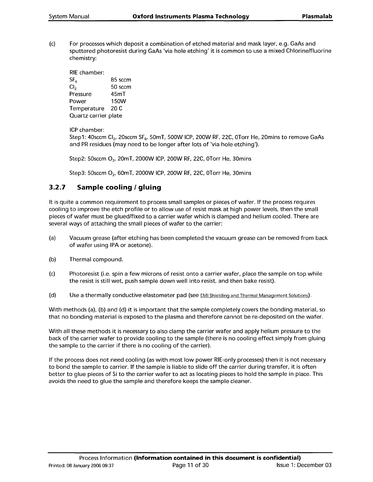
(c)
For processes
which
deposit
a
combination
of
etched material and mask layer, e.g. GaAs and
sputtered
photoresist
during
GaAs 'via
hole
etching'
it
is
common
to
use a mixed
Chlorine/fluorine
chemistry:
RIE
chamber:
SF
6
85
sccm
CI
2
50
sccm
Pressure 45mT
Power
150VV
Temperature
20 C
Quartz
carrier
plate
ICP
chamber:
Step1:
40sccm
C1
2
,
20sccm
SF
6
,
50mT,
500VV
ICP,
200VV
RF,
22C,
OTorr He, 20mins
to
remove GaAs
and
PR
residues (may need
to
be
longer
after
lots
of
'via
hole
etching').
Step2:
50sccm
°
2
,
20mT,
2000VV
ICP,
200VV
RF,
22C,
OTorr He, 30mins
Step3:
50sccm
°
2
,
60mT,
2000VV
ICP,
200VV
RF,
22C,
OTorr He, 30mins
3.2.7
Sample
cooling
I
gluing
It
is
quite
a
common
requirement
to
process small samples
or
pieces
of
wafer.
If
the
process requires
cooling
to
improve
the
etch
profile
or
to
allow
use
of
resist mask
at
high
power
levels,
then
the
small
pieces
of
wafer
must be
glued/fixed
to
a carrier
wafer
which
is
clamped and
helium
cooled. There are
several ways
of
attaching
the
small pieces
of
wafer
to
the
carrier:
(a)
Vacuum grease
(after
etching
has been
completed
the
vacuum grease can be removed
from
back
of
wafer
using IPA
or
acetone).
(b) Thermal
compound.
(c)
Photoresist (i.e. spin a
few
microns
of
resist
onto
a carrier
wafer,
place
the
sample on
top
while
the
resist
is
still
wet,
push sample
down
well
into
resist, and
then
bake resist).
(d)
Use
a
thermally
conductive elastometer pad
(see
EMI Shielding and Thermal
Manaqement
Solutions).
VVith
methods
(a), (b) and (d)
it
is
important
that
the
sample
completely
covers
the
bonding
material,
so
that
no
bonding
material
is
exposed
to
the
plasma and
therefore
cannot
be re-deposited on
the
wafer.
VVith
all these
methods
it
is
necessary
to
also clamp
the
carrier
wafer
and apply
helium
pressure
to
the
back
of
the
carrier
wafer
to
provide
cooling
to
the
sample
(there
is
no
cooling
effect
simply
from
gluing
the
sample
to
the
carrier
if
there
is
no
cooling
of
the
carrier).
If
the
process does
not
need
cooling
(as
with
most
low
power
RIE-only processes)
then
it
is
not
necessary
to
bond
the
sample
to
carrier.
If
the
sample
is
liable
to
slide
off
the
carrier
during
transfer,
it
is
often
better
to
glue
pieces
of
Si
to
the
carrier
wafer
to
act
as
locating pieces
to
hold
the
sample in place. This
avoids
the
need
to
glue
the
sample and
therefore
keeps
the
sample cleaner.
Process
Information
(Information
contained
in
this
document
is
confidential)
Printed: 08 January 2006 09:37 Page
11
of
30
Issue
1: December 03
Plasma
lab
Oxford Instruments Plasma Technology
System Manual
3.2.8
Use
of
helium
backing
for
effective
process
temperature
control
3.2.8.1 Scope
For all systems
with
wafer
clamping and
helium
backing
for
wafer
temperature
control.
i.e. Plasmalab
System 100
with
ICP
65,
180 and 380 sources. Also, occasionally
RIE
133 systems and
RIE
80
Plus.
3.2.8.2
Purpose
It
is
important
to
ensure
that
the
helium
is
sealed adequately
behind
the
wafer.
If
the
helium
is
leaking
out
past
the
wafer
with
a
poor
seal against
the
table,
the
thermal
contact
to
the
temperature-controlled
table
will
be degraded. The
wafer
will
then
heat
up
more
than
expected and
the
process results may
suffer. For example, in
SiOz
etching
the
profile
may become
partially
isotropic and/or any photoresist
masking used may
burn
too
easily.
3.2.8.3
Simple
Method
to
check
Helium
backing
(a)
If
the
wafer
is
sealing
the
helium
effectively,
the
measured He
flow
will
be
less
than
that
when
no
wafer
is
present.
(b) Set a range
of
He pressures and
note
the
measured
helium
flows
with
no
wafer
loaded. (Set all
process
gases,
RF
and pressure
to
zero and
work
in
'manual'
mode.)
(c)
Load a
blank
Si
wafer
of
the
correct size
(if
the
system
is
a standard single
wafer
type) and
note
the
He
flows
for
the
same range
of
set He pressures.
(d) Load a typical customer
wafer
(e.g.
with
a
thick
SiOz
layer) and
note
the
He
flows
for
the
same
range
of
set He pressures.
If
a carrier
is
appropriate
for
the
system, use
that.
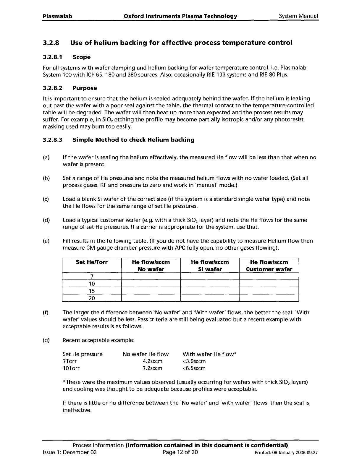
(e)
Fill results
in
the
following
table.
(If
you
do
not
have
the
capability
to
measure Helium
flow
then
measure CM
gauge
chamber pressure
with
APC
fully
open,
no
other
gases
flowing).
Set
Herrorr He flow/seem He flow/seem He flow/seem
No
wafer
Si
wafer
Customer
wafer
7
10
15
20
(f) The
larger
the
difference
between
'No
wafer'
and
'With
wafer'
flows,
the
better
the
seal.
'With
wafer'
values should be
less.
Pass
criteria are still being evaluated
but
a recent example
with
acceptable results
is
as
follows.
(g) Recent acceptable example:
Set
He
pressure
7Torr
10Torr
No
wafer
He
flow
4.2sccm
7.2sccm
With
wafer
He
flow*
<3.9sccm
<6.5sccm
*These
were
the
maximum
values observed (usually occurring
for
wafers
with
thick
SiOz
layers)
and
cooling
was
thought
to
be adequate because profiles
were
acceptable.
If
there
is
little
or
no
difference
between
the
'No
wafer'
and
'with
wafer'
flows,
then
the
seal
is
ineffective.
Process
Information
(Information
contained in this
document
is
confidential)
Issue
1:
December 03 Page 12
of
30 Printed: 08 January 2006 09:37