Oxford-100-Manual.pdf - 第160页
Plasma lab Oxford Instruments Plasma Technology System Manual 3.3 3.3.1 PECVD processes PECVD operating parameter ranges For a PECVD tool the typical process operating ranges are: Total gas flows = 150 to 3000sccm. The m…
System
Manual
Oxford
Instruments
Plasma Technology
Plasma
lab
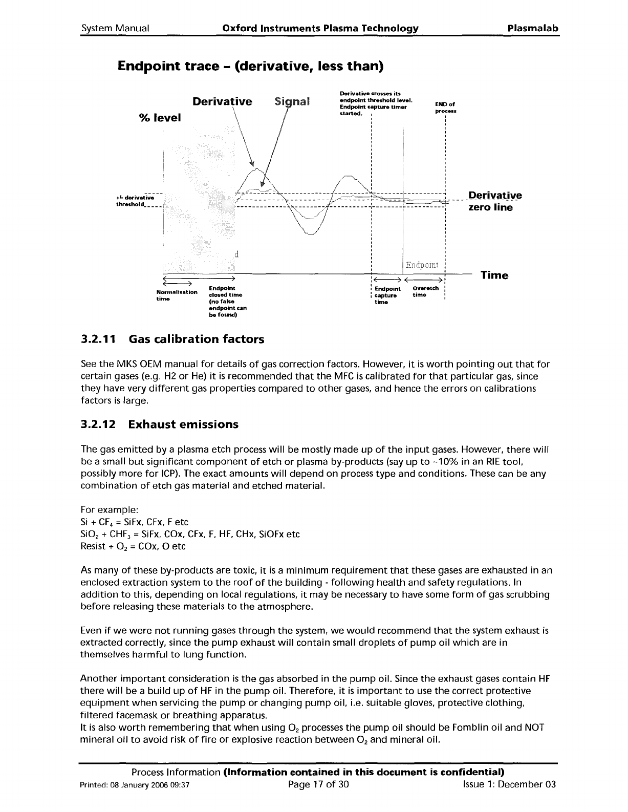
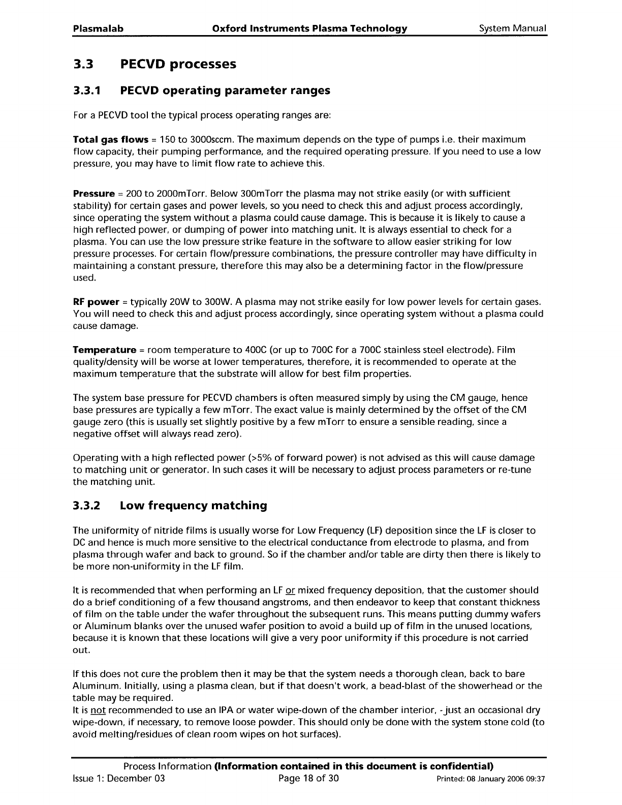
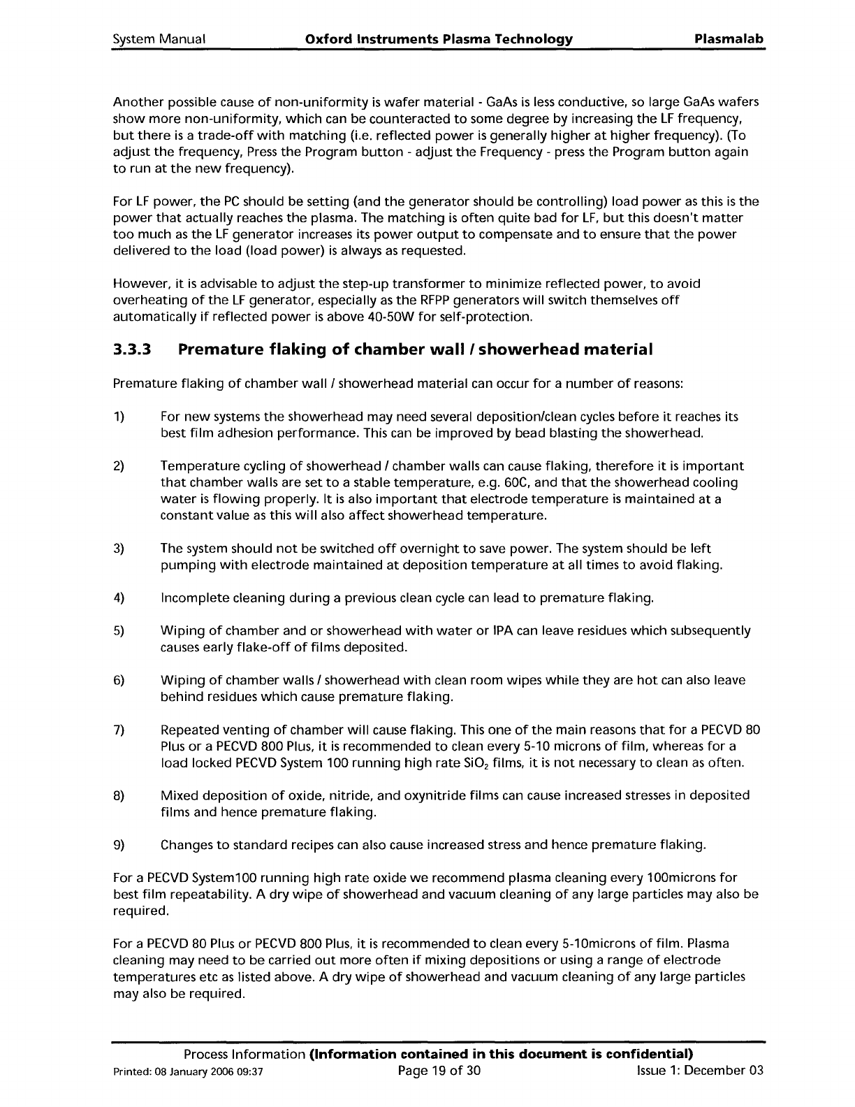
Endpoint
trace
-
(derivative,
less
than)
Time
)
process
ENOof
Overetch
time
:~(
,
:
Endpoint
I
capture
time
Derivative
crosses
its
endpoint
threshold
level.
Endpoint
captLR'e
timer
started.
Sigmd
d
Endpoint
closed
time
(nofals8
endpoint
can
be
found)
Derivative
\
\
:
\ i
~
i
/~'"
i
:0:~~~::::/~:::::::~---~";:'ir~z-"
\~
:
,
,
,
,
,
,
,
,
,
Normalisation
time
%
level
+/-
derivative
3.2.11
Gas
calibration
factors
See
the
MKS OEM manual
for
details
of
gas correction factors. However,
it
is
worth
pointing
out
that
for
certain gases (e.g.
H2
or
He)
it
is
recommended
that
the
MFC
is
calibrated
for
that
particular
gas, since
they
have very
different
gas properties compared
to
other
gases, and hence
the
errors on calibrations
factors
is
large.
3.2.12
Exhaust
emissions
The gas
emitted
by a plasma etch process
will
be mostly made
up
of
the
input
gases.
However,
there
will
be a small
but
significant
component
of
etch
or
plasma by-products
(say
up
to
-10%
in an
RIE
tool,
possibly
more
for
ICP).
The exact
amounts
will
depend
on process
type
and conditions. These can be any
combination
of
etch gas
material
and etched material.
For example:
Si
+
CF
4
=
SiFx,
CFx,
Fetc
Si0
2
+
CHF
3
=
SiFx,
COx,
CFx,
F,
HF,
CHx,
SiOFx
etc
Resist
+ O
2
=
COx,
0 etc
As
many
of
these by-products are toxic,
it
is
a
minimum
requirement
that
these gases are exhausted in an
enclosed
extraction
system
to
the
roof
of
the
building
-
following
health
and safety regulations. In
addition
to
this,
depending
on
local regulations,
it
may be necessary
to
have some
form
of
gas scrubbing
before
releasing these materials
to
the
atmosphere.
Even
if
we
were
not
running
gases
through
the
system,
we
would
recommend
that
the
system exhaust
is
extracted correctly, since
the
pump
exhaust
will
contain small
droplets
of
pump
oil
which
are in
themselves
harmful
to
lung
function.
Another
important
consideration
is
the
gas absorbed in
the
pump
oil. Since
the
exhaust gases contain
HF
there
will
be a
build
up
of
HF
in
the
pump
oil. Therefore,
it
is
important
to
use
the
correct
protective
equipment
when
servicing
the
pump
or
changing
pump
oil, i.e. suitable gloves, protective
clothing,
filtered
facemask
or
breathing
apparatus.
It
is
also
worth
remembering
that
when
using O
2
processes
the
pump
oil should be Fomblin
oil
and NOT
mineral
oil
to
avoid risk
of
fire
or
explosive reaction
between
O
2
and mineral oil.
Process
Information
(Information
contained
in
this
document
is
confidential)
Printed: 08 January 2006 09:37 Page
17
of
30
Issue
1:
December 03
Plasma
lab
Oxford
Instruments
Plasma
Technology
System
Manual
3.3
3.3.1
PECVD
processes
PECVD
operating
parameter
ranges
For a
PECVD
tool
the
typical process
operating
ranges are:
Total
gas
flows
=150
to
3000sccm. The
maximum
depends on
the
type
of
pumps i.e.
their
maximum
flow
capacity,
their
pumping
performance, and
the
required
operating
pressure.
If
you
need
to
use a
low
pressure,
you
may have
to
limit
flow
rate
to
achieve this.
Pressure =200
to
2000mTorr.
Below
300mTorr
the
plasma may
not
strike easily (or
with
sufficient
stability)
for
certain gases and
power
levels,
so
you
need
to
check this and adjust process accordingly,
since
operating
the
system
without
a plasma could cause damage. This
is
because
it
is
likely
to
cause a
high
reflected power,
or
dumping
of
power
into
matching
unit.
It
is
always essential
to
check
for
a
plasma. You can use
the
low
pressure strike
feature
in
the
software
to
allow
easier
striking
for
low
pressure processes. For certain flow/pressure combinations,
the
pressure
controller
may have
difficulty
in
maintaining
a constant pressure,
therefore
this may also be a
determining
factor
in
the
flow/pressure
used.
RF
power
=typically 20W
to
300W. A plasma may
not
strike easily
for
low
power
levels
for
certain
gases.
You
will
need
to
check this and adjust process accordingly, since
operating
system
without
a plasma could
cause damage.
Temperature
=
room
temperature
to
400C
(or
up
to
700C
for
a 700C stainless steel electrode). Film
quality/density
will
be worse
at
lower
temperatures,
therefore,
it
is
recommended
to
operate
at
the
maximum
temperature
that
the
substrate
will
allow
for
best
film
properties.
The system base pressure
for
PECVD
chambers
is
often
measured simply by using
the
CM gauge, hence
base pressures are typically a
few
mTorr. The exact value
is
mainly
determined
by
the
offset
of
the
CM
gauge
zero (this
is
usually set
slightly
positive
by
a
few
mTorr
to
ensure a sensible reading, since a
negative
offset
will
always read zero).
Operating
with
a
high
reflected
power
(>5%
of
forward
power)
is
not
advised
as
this
will
cause damage
to
matching
unit
or
generator. In such
cases
it
will
be necessary
to
adjust process parameters
or
re-tune
the
matching
unit.
3.3.2
Low
frequency
matching
The
uniformity
of
nitride
films
is
usually worse
for
Low
Frequency
(LF)
deposition
since
the
LF
is
closer
to
DC
and hence
is
much
more
sensitive
to
the
electrical conductance
from
electrode
to
plasma, and
from
plasma
through
wafer
and back
to
ground.
So
if
the
chamber
and/or
table
are
dirty
then
there
is
likely
to
be
more
non-uniformity
in
the
LF
film.
It
is
recommended
that
when
performing
an
LF
or
mixed frequency deposition,
that
the
customer should
do
a
brief
conditioning
of
a
few
thousand angstroms, and
then
endeavor
to
keep
that
constant thickness
of
film
on
the
table
under
the
wafer
throughout
the
subsequent runs. This means
putting
dummy
wafers
or
Aluminum
blanks over
the
unused
wafer
position
to
avoid a
build
up
of
film
in
the
unused locations,
because
it
is
known
that
these locations
will
give a very
poor
uniformity
if
this procedure
is
not
carried
out.
If
this does
not
cure
the
problem
then
it
may
be
that
the
system needs a
thorough
clean, back
to
bare
Aluminum.
Initially, using a plasma clean,
but
if
that
doesn't
work,
a bead-blast
of
the
showerhead
or
the
table
may be required.
It
is
not
recommended
to
use an
IPA
or
water
wipe-down
of
the
chamber
interior,
-just
an occasional
dry
wipe-down,
if
necessary,
to
remove loose
powder.
This should
only
be
done
with
the
system stone cold
(to
avoid meltinglresidues
of
clean
room
wipes
on
hot
surfaces).
Process
Information
(Information
contained
in
this
document
is
confidential)
Issue
1:
December 03 Page 18
of
30 Printed: 08 January 2006 09:37
System
Manual
Oxford
Instruments
Plasma Technology
Plasma
lab
Another
possible cause
of
non-uniformity
is
wafer
material - GaAs
is
less
conductive,
so
large GaAs wafers
show
more
non-uniformity,
which
can
be
counteracted
to
some degree by increasing
the
LF
frequency,
but
there
is
a
trade-off
with
matching
(i.e. reflected
power
is
generally
higher
at
higher
frequency). (To
adjust
the
frequency,
Press
the
Program
button
- adjust
the
Frequency - press
the
Program
button
again
to
run
at
the
new
frequency).
For
LF
power,
the
PC
should
be
setting
(and
the
generator
should be
controlling)
load
power
as
this
is
the
power
that
actually reaches
the
plasma. The
matching
is
often
quite
bad
for
LF,
but
this
doesn't
matter
too
much
as
the
LF
generator
increases its
power
output
to
compensate and
to
ensure
that
the
power
delivered
to
the
load (load
power)
is
always
as
requested.
However,
it
is
advisable
to
adjust
the
step-up
transformer
to
minimize
reflected power,
to
avoid
overheating
of
the
LF
generator,
especially
as
the
RFPP
generators
will
switch themselves
off
automatically
if
reflected
power
is
above 40-50W
for
self-protection.
3.3.3
Premature
flaking
of
chamber
wall
I
showerhead
material
Premature
flaking
of
chamber
wall/
showerhead
material
can occur
for
a
number
of
reasons:
1)
For
new
systems
the
showerhead may need several deposition/clean cycles
before
it
reaches its
best
film
adhesion performance. This can be
improved
by bead blasting
the
showerhead.
2)
Temperature
cycling
of
showerhead / chamber walls can cause
flaking,
therefore
it
is
important
that
chamber walls are set
to
a stable
temperature,
e.g.
60C,
and
that
the
showerhead
cooling
water
is
flowing
properly.
It
is
also
important
that
electrode
temperature
is
maintained
at
a
constant
value
as
this
will
also
affect
showerhead
temperature.
3)
The system should
not
be switched
off
overnight
to
save power. The system should be
left
pumping
with
electrode
maintained
at
deposition
temperature
at
all times
to
avoid
flaking.
4)
Incomplete
cleaning
during
a previous clean cycle can lead
to
premature
flaking.
5)
Wiping
of
chamber and
or
showerhead
with
water
or
IPA can leave residues
which
subsequently
causes early
flake-off
of
films deposited.
6)
Wiping
of
chamber walls / showerhead
with
clean
room
wipes
while
they
are
hot
can also leave
behind
residues
which
cause
premature
flaking.
7)
Repeated
venting
of
chamber
will
cause
flaking.
This one
of
the
main
reasons
that
for
a
PECVD
80
Plus
or
a
PECVD
800 Plus,
it
is
recommended
to
clean every 5-10 microns
of
film,
whereas
for
a
load locked
PECVD
System 100
running
high
rate
SiOz
films,
it
is
not
necessary
to
clean
as
often.
8)
Mixed
deposition
of
oxide,
nitride,
and
oxynitride
films can cause increased stresses in deposited
films and hence
premature
flaking.
9)
Changes
to
standard recipes can also cause increased stress and hence
premature
flaking.
For a
PECVD
System100
running
high
rate
oxide
we
recommend plasma cleaning every 100microns
for
best
film
repeatability.
A
dry
wipe
of
showerhead and vacuum cleaning
of
any large particles may also be
required.
For a
PECVD
80 Plus
or
PECVD
800 Plus,
it
is
recommended
to
clean every
5-1
Omicrons
of
film. Plasma
cleaning may need
to
be
carried
out
more
often
if
mixing
depositions
or
using a range
of
electrode
temperatures
etc
as
listed above. A
dry
wipe
of
showerhead and vacuum cleaning
of
any large particles
may also be required.
Process
Information
(Information
contained
in
this
document
is
confidential)
Printed: 08 January 2006 09:37 Page 19
of
30
Issue
1:
December 03