Oxford-100-Manual.pdf - 第182页
Plasma lab and lonfab NOTES: Issue 2: December 01 Oxford Instruments Plasma Technology Measurement of RF & Microwave Emissions Page 4 of 4 System Manual Printed: 21-Dec-04, 13:43
System
Manual
Oxford
Instruments
Plasma
Technology
Plasma
lab
and
lonfab
It
is
strongly
recommended
that
the
operation
of
all safety interlocks should be tested
at
the
same time,
whenever
an
RF
or
Microwave
leakage test
is
performed.
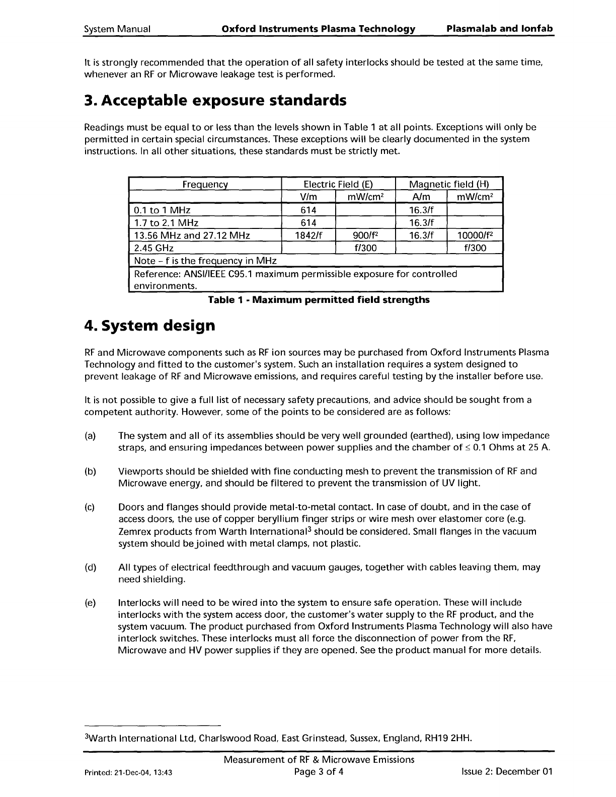
3. Acceptable exposure standards
Readings must be equal
to
or
less
than
the
levels shown
in
Table 1
at
all points. Exceptions
will
only
be
permitted
in certain special circumstances. These exceptions
will
be
clearly
documented
in
the
system
instructions. In all
other
situations, these standards
must
be strictly met.
Frequency Electric Field
(E)
Ma!=jnetic
field
(H)
VIm mWlcm
2
AIm mW/cm
2
0.1
to
1
MHz
614
16.3/f
1.7to2.1
MHz
614
16.3/f
13.56
MHz
and 27.12
MHz
1842/f
900/f2
16.3/f
10000/f2
2.45 GHz
fl300
fl300
Note
- f
is
the
frequency
in
MHz
Reference:
ANSI/lEEE
C95.1
maximum
permissible exposure
for
controlled
environments.
Table
1 •
Maximum
permitted
field
strengths
4. System design
RF
and
Microwave
components such
as
RF
ion
sources may be purchased
from
Oxford
Instruments Plasma
Technology and
fitted
to
the
customer's system.
Such
an
installation
requires a system designed
to
prevent
leakage
of
RF
and
Microwave
emissions, and requires careful
testing
by
the
installer
before
use.
It
is
not
possible
to
give a
full
list
of
necessary safety precautions, and advice should be
sought
from
a
competent
authority.
However, some
of
the
points
to
be considered are
as
follows:
(a)
The system and all
of
its assemblies should be very
well
grounded
(earthed), using
low
impedance
straps, and ensuring impedances
between
power
supplies and
the
chamber
of
~
0.1
Ohms
at
25
A.
(b)
Viewports
should be shielded
with
fine
conducting
mesh
to
prevent
the
transmission
of
RF
and
Microwave
energy, and should be
filtered
to
prevent
the
transmission
of
UV
light.
(c)
Doors and flanges should
provide
metal-to-metal
contact. In
case
of
doubt,
and
in
the
case
of
access
doors,
the
use
of
copper
beryllium
finger
strips
or
wire
mesh over elastomer core (e.g.
Zemrex products
from
Warth
International
3
should be considered. Small flanges in
the
vacuum
system should
bejoined
with
metal
clamps,
not
plastic.
(d)
All
types
of
electrical
feedthrough
and vacuum gauges,
together
with
cables leaving them, may
need shielding.
(e)
Interlocks
will
need
to
be
wired
into
the
system
to
ensure safe
operation.
These
will
include
interlocks
with
the
system
access
door,
the
customer's
water
supply
to
the
RF
product,
and
the
system vacuum. The
product
purchased
from
Oxford
Instruments Plasma Technology
will
also have
interlock
switches. These interlocks
must
all force
the
disconnection
of
power
from
the
RF,
Microwave
and HV
power
supplies
if
they
are opened.
See
the
product
manual
for
more
details.
3Warth
International
Ltd, Charlswood Road, East Grinstead,
Sussex,
England, RH19 2HH.
Printed: 21-Dec-04, 13:43
Measurement
of
RF
&
Microwave
Emissions
Page 3
of
4
Issue
2:
December
01
Plasma
lab
and
lonfab
NOTES:
Issue
2:
December
01
Oxford
Instruments
Plasma
Technology
Measurement
of
RF
&
Microwave
Emissions
Page 4
of
4
System Manual
Printed: 21-Dec-04, 13:43
System
Manual
Oxford
Instruments
Plasma
Technology
Plasma
lab
and
lonfab
Appendix
B
Operation
and
maintenance
of
turbomolecular
pumps
Appendix
B
Operation
and
maintenance
of
turbomolecular
pumps
1
1
Maintenance
for
all
Turbo
Pumps 2
2
Maintenance
for
Alcatal
ATP/ACT
Turbo
pumps
3
2.1
Re-greasing
of
turbo
pumps
fitted
to
process chambers 3
2.2 2000
to
8000 hours
(3
to
12 months):
pump
relubrication
3
Printed: 21-Dec-04, 13:44
Operation
and
Maintenance
of
Turbo
Pumps
Page 1
of
4
Issue
3:
June 02