Oxford-100-Manual.pdf - 第209页
Installation Data Oxford Instruments Plasma Technology PlasmalabSystem 1 00 T" GAS INLET LINES 20 - SECONDARY GAS OUTLET LINE TO SYSTEM (ONLY USED IF A SPLIT MANIFOLD ISFITIED) LOCATION OF FIXING HOLES, EACH 6.6 mm …
PlasmalabSystem
100
Oxford
Instruments
Plasma Technology
Installation Data
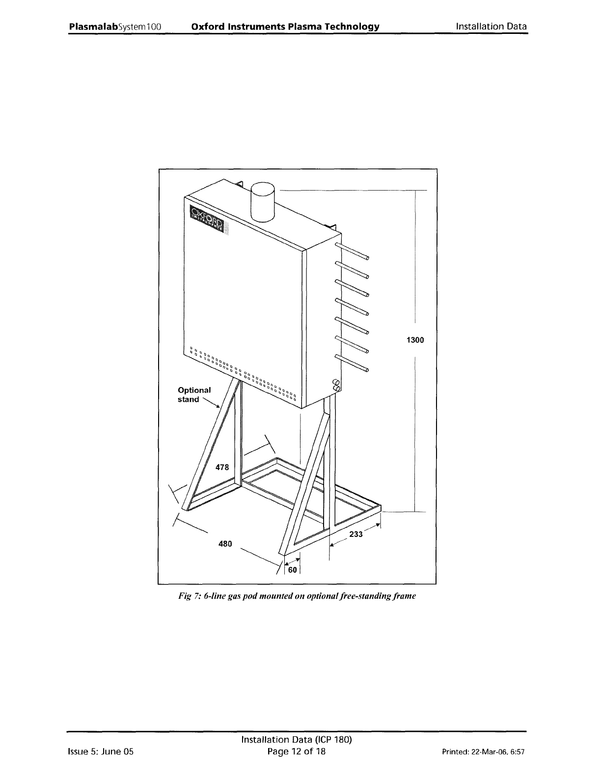
Optional
stand
~
480
-----
_-_._--
1300
Issue
5:
June 05
Fig
7:
6-line gas
pod
mountedon optionalfree-standing
frame
Installation Data
OCP
180)
Page 12
of
18 Printed: 22-Mar-06. 6:57
Installation Data
Oxford
Instruments
Plasma
Technology
PlasmalabSystem100
T"
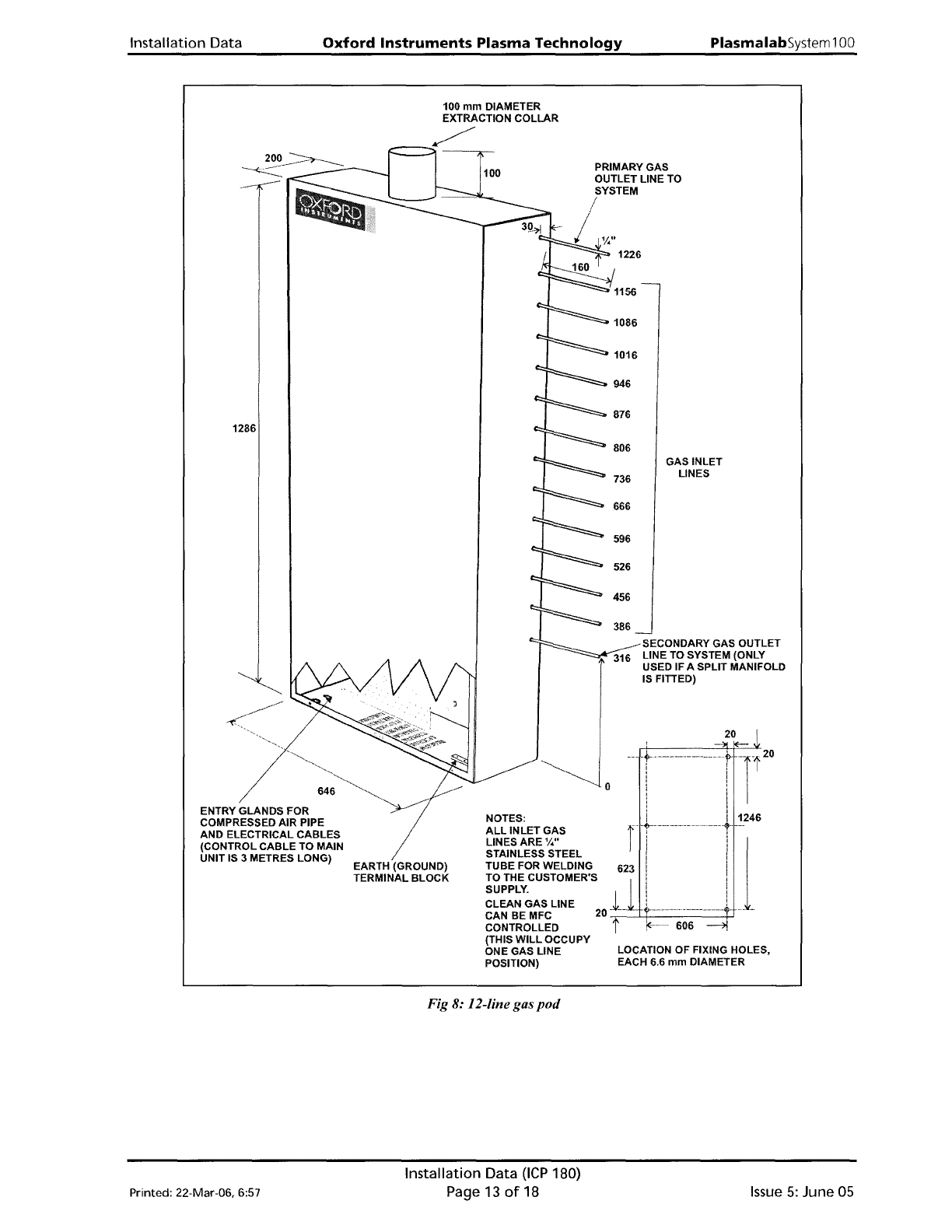
GAS INLET
LINES
20
-SECONDARY GAS OUTLET
LINE
TO
SYSTEM (ONLY
USED IF A SPLIT MANIFOLD
ISFITIED)
LOCATION OF FIXING HOLES,
EACH 6.6
mm
DIAMETER
o
PRIMARY GAS
OUTLET LINE TO
SYSTEM
/
I iY."
--
..
'r-
-
-----.-.--
----.--..
,
I i
I
1 i
~1~~W~~1
~~s
rt---------
....
---+
1246
STAINLESS STEEL '
i 1
TUBE FOR WELDING 623 i i
~~X~:::ER'S"lJ
L--1
..
CONTROLLED t
~......
606
-c>I
(THIS
WILL
OCCUpy
ONE GAS LINE
POSITION)
100
100
mm
DIAMETER
EXTRACTION COLLAR
~
t===~
EARTH (GROUND)
TERMINAL BLOCK
1286
ENTRY GLANDS FOR
COMPRESSED AIR PIPE
AND ELECTRICAL CABLES
(CONTROL
CABLE
TO MAIN
UNIT IS 3 METRES LONG)
Fig 8: I2-line gas
pod
Printed: 22-Mar-06. 6:57
Installation
Data
(ICP
180)
Page 13
of
18
Issue
5:
June
05
PiasmaiabSystem100
s.
Services
Oxford
Instruments
Plasma
Technology
Installation Data
The
required
services are listed in
the
following
sub-sections. For
full
details
of
services
specifications
including
connection diagrams, electrical connection schematic etc., read in
conjunction
with
the
Oxford
Instruments Plasma Technology 'Services Specifications
for
Plasmalab
and
lonfab
Systems' document.
5.1 Electrical
Supply
requirement
Function
Connection
Parameter
System electrical
Cable
(4
meters
Voltage
supply (208V
long)
Current
system)
Frequency
Phases
System electrical
Cable
(4
meters
Voltage
supply (415V
long)
system)
Current
Frequency
Phases
5.2
Water
Cooling
requirement
Function
Connection
Parameter
Process
turbo
'//'
stainless steel Flow
Swagelok
Temperature
RF
Generator and
3/
8
"
stainless steel
Flow
ICP
Swagelok
Temperature
ICP
&
AMU
3/
8
"
stainless steel
Flow
Swagelok
Temperature
Load lock
turbo
(if
'/4" stainless steel
Flow
required)
Swagelok
Temperature
5.3
Lower
Electrode
Cooling
requirement
Specification
208Vac ±10%
50A
50/60
Hz
3 phase, N + E
380Vac
-10%
to
415Vac
+6%
50A
50/60
Hz
3 phase, N + E
Specification
1 lpm (0.27
gpm
(US»
15
-
25°C
(59 -
77°F)
8 Ipm (2.12
gpm
(US»
10 -
25°C
(50 - 77°F)
2 lpm (0.53
gpm
(US»
10 -
25°C
(50 - 77°F)
1
lpm
(0.27
gpm
(US»
15
-
25°C
(59 -
77°F)
Function
Liquid cooled
lower
electrode
LN2
Cryo cooled
lower
electrode
Connection
3/
8
"
stainless steel
Swagelok
to
heater
/
chiller
unit
%"
stainless steel
Swagelok
to
dewar
Parameter
Flow
Temperature
Flow
Specification
2
lpm
(0.53
gpm
(US»
As
required by process
As
required
by process
5.4
Compressed
Air
requirement
Function
System CDA
Gas
pod
CDA
Connection
4mm
push-fit
Legris
4mm
push-fit
Legris
Parameter
Flow
Pressure
Flow
Pressure
Specification
5
lpm
(0.2 cfm)
(combined
with
gas
pod)
4.0 - 6.0 Bar (60 - 90
psi)
5 lpm (0.2 cfm)
(combined
with
system)
4.0 - 6.0 Bar (60 - 90
psi)
Issue
5:
June
05
Installation Data
(ICP
180)
Page
14
of
18 Printed: 22-Mar-06, 6:57