Oxford-100-Manual.pdf - 第217页
System Manual Oxford Instruments Plasma Technology All OIPT Systems The flow-setting knob can be on the upstream or downstream side of the tube. If it is upstream (below the tube), the pressure in the tube is close to th…
All
OIPT Systems
1
Rotameters
Oxford
Instruments
Plasma
Technology
System
Manual
A
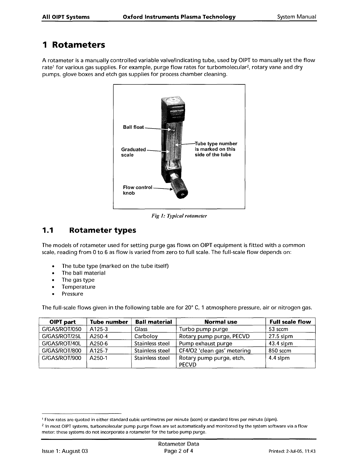
rotameter
is
a
manually
controlled
variable valvelindicating tube, used
by
OIPT
to
manually
set
the
flow
rate'
for
various gas supplies. For example,
purge
flow
rates
for
turbomolecular
2
,
rotary
vane and
dry
pumps, glove boxes and etch gas supplies
for
process chamber cleaning.
Ball
float
Graduated
scale
Flow
control
__
....
knob
Tube type
number
is marked
on
this
side
of
the tube
Fig 1: Typical rotameter
1.1
Rotameter
types
The models
of
rotameter
used
for
setting
purge
gas
flows
on
OIPT
equipment
is
fitted
with
a
common
scale, reading
from
0
to
6
as
flow
is
varied
from
zero
to
full
scale. The full-scale
flow
depends on:
• The
tube
type
(marked on
the
tube
itself)
• The ball material
• The gas
type
•
Temperature
• Pressure
The full-scale
flows
given
in
the
following
table
are
for
20
0
C,
1 atmosphere pressure, air
or
nitrogen
gas.
OIPT
part
Tube
number
Ball
material
Normal
use Full scale
flow
G/GAS/ROT
1050
A125-3
Glass
Turbo
pump
pur!=le
53
sccm
G/GAS/ROT/25L A250-4
Carboloy
Rotary
pump
purqe,
PECVD
27.5 slpm
G/GAS/ROT/40L A250-6
Stainless steel Pump exhaust
purqe
43.4 slpm
G/GAS/ROT
1800
A125-7 Stainless steel CF4/02 'clean
!=las'
meterinq
850
sccm
G/GAS/ROT/900 A250-1
Stainless steel Rotary
pump
purge, etch, 4.4 slpm
PECVD
1 Flow rates are
quoted
in
either
standard cubic centimetres per
minute
(seem)
or
standard litres per
minute
(slpm).
2 In most
OIPT
systems.
turbomolecular
pump
purge
flows
are set
automatically
and
monitored
by
the
system
software
via a
flow
meter: these systems
do
not
incorporate
a
rotameter
for
the
turbo
pump
purge.
Issue
1:
August
03
Rotameter Data
Page 2
of
4
Printed: 2-Jul-05.
11
:43
System
Manual
Oxford
Instruments
Plasma Technology
All OIPT Systems
The
flow-setting
knob
can be
on
the
upstream
or
downstream
side
of
the
tube.
If
it
is
upstream
(below
the
tube),
the
pressure
in
the
tube
is
close
to
the
exit
pressure,
which
should be close
to
1
bar
absolute
for
pump
or
exhaust pipe
purging.
If
the
knob
is
downstream
(above
the
tUbe)
the
pressure in
the
tube
is
close
to
the
supply
pressure
of
the
gas. This
method
is
normally
used
if
the
exit
pressure
is
below
atmospheric
pressure,
which
is
often
the
case
in
turbomolecular
pump
purging.
If
in
doubt,
control
downstream
is
always safe, because
the
ball
float
will
operate
normally
and
the
purge
flow
will
be
slightly
higher
than
given in
the
table.
1.2
Setting
the
required
purge
flow
rate
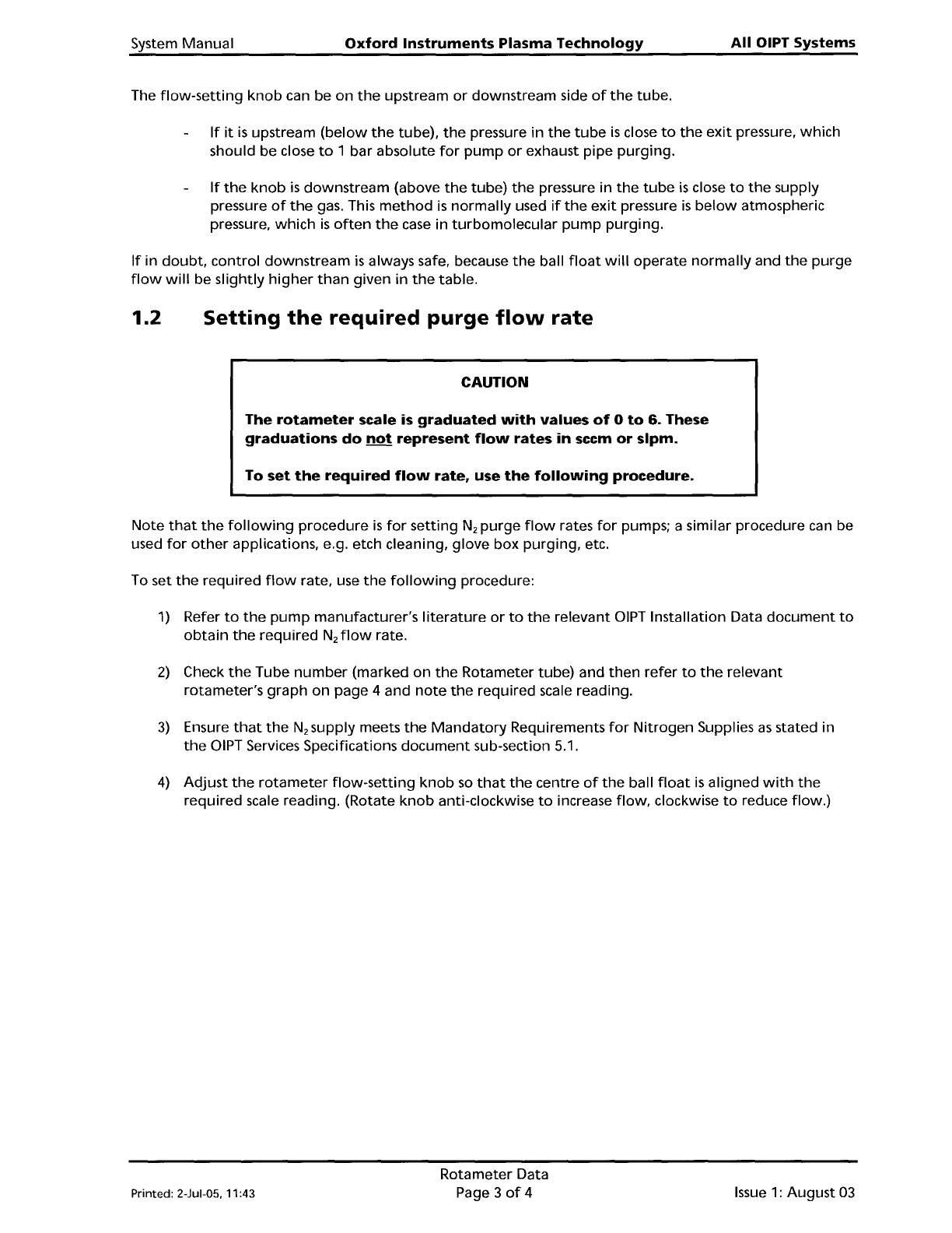
CAUTION
The
rotameter
scale is
graduated
with
values
of
0
to
6. These
graduations
do
not
represent
flow
rates
in
seem
or
slpm.
To
set
the
required
flow
rate,
use
the
following
procedure.
Note
that
the
following
procedure
is
for
setting
N
2
purge
flow
rates
for
pumps; a similar procedure can be
used
for
other
applications, e.g. etch cleaning,
glove
box
purging,
etc.
To set
the
required
flow
rate, use
the
following
procedure:
1)
Refer
to
the
pump
manufacturer's
literature
or
to
the
relevant DIPT Installation Data
document
to
obtain
the
required
N
2
flow
rate.
2)
Check
the
Tube
number
(marked
on
the
Rotameter
tube)
and
then
refer
to
the
relevant
rotameter's
graph
on
page 4 and
note
the
required scale reading.
3)
Ensure
that
the
N
2
supply meets
the
Mandatory
Requirements
for
Nitrogen
Supplies
as
stated in
the
DIPT Services Specifications
document
sub-section 5.1.
4)
Adjust
the
rotameter
flow-setting
knob
so
that
the
centre
of
the
ball
float
is
aligned
with
the
required
scale reading. (Rotate
knob
anti-clockwise
to
increase
flow,
clockwise
to
reduce
flow.)
Printed: 2-Jul-05.
11
:43
Rotameter Data
Page 3
of
4
Issue
1:
August
03
All
OIPT Systems
Oxford
Instruments
Plasma
Technology
System Manual
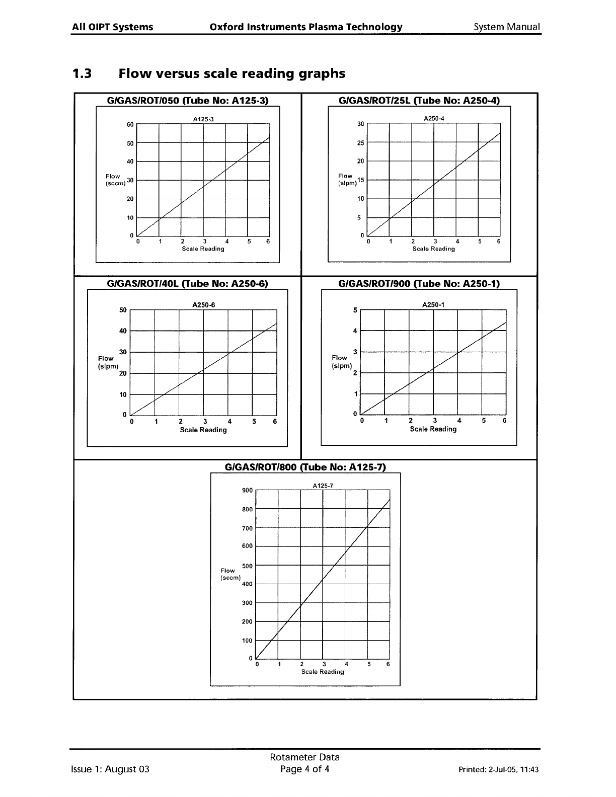
1.3
Flow
versus scale
reading
graphs
G/GAS/ROT/050 (Tube No: A
125-3)
G/GAS/ROT/25L (Tube No:
A250-4)
A125·3
A250-4
60
30
25
/
50
,/
V
40
./
20
,/
/
V
Flow
/'
Flow
/
(seem)
30
/'
(slpm)15
/
20
/
10
1:/
/
5
01
/
/
0 1 2 3 4 5 6 0 1 2 3 4 5 6
Scale
Reading
Scale
Reading
G/GAS/ROT/40L
(Tube
No:
A250-6)
G/GAS/ROT/900
(Tube
No:
A250-1)
A250-6
A250-1
50
5
40
./
4
./
/'
V
30
/
3
/
Flow
/
Flow
/
(slpm)
(slpm)
20
/
2
/
10
./
1 V
/
/
v
0/
0
0 1 2 3 4 5 6
0 1 2 3 4 5 6
Scale Reading
Scale Reading
G/GAS/ROT/aOO (Tube No:
A125-7)
A125-7
900
/
800
/
700
/
600
500
/
Flow
V
(seem)
400
/
300
200
/
V
100 /
0/
0
1 2
3
4
5 6
Scale
Reading
Issue
1:
August
03
Rotameter Data
Page 4
of
4 Printed: 2-Jul-05,
11
:43