Oxford-100-Manual.pdf - 第249页
Equipment Manual Oxford Instruments Plasma Technology Plasma lab ICP 180 3.4 Graphs of typical operating characteristics High ion flux to the wafer A figure of merit for the ICP is the ion current density at the wafer, w…
Plasma
lab
ICP
180
Oxford
Instruments
Plasma
Technology
Equipment
Manual
The
Plasma
lab
Ie
P180
is
an assembly
which
can be
fitted
to
a
Plasma
lab
System
100 chamber in place
of
the
standard chamber lid. The assembly comprises a chamber lid on
which
is
mounted
the
ICP
discharge
chamber, an
automatch
unit
and a shielding cover.
The chamber lid
is
secured
to
the
process chamber
by
hinges
which
allow
it
to
be
tilted
for
process
chamber maintenance. The lid
is
water
cooled
by
a circular
cooling
element. Vacuum sealing
between
the
lid and
the
process chamber
is
provided
by an
a-ring.
A
mounting
plate
attached
to
the
lid supports
the
automatch
unit.
The discharge chamber comprises an insulated
tube
sealed
at
its
top
and
bottom
by a-rings. The insulated
tube
is
cooled
at
its
top
and
bottom
by
cooling
collars.
An
electrostatic shield surrounds
the
insulated
tube. A
water-cooled
RF
induction
coil,
supported
by
two
clamping assemblies,
is
located outside
of
the
insulated
tube
and electrostatic shield.
The
top
of
the
discharge chamber
is
a cover
plate
which
incorporates an
extraction
cover,
endpoint
detector
port.
process gas inlet. pressure
relief
valve and a circular
cooling
element.
Air
is
drawn
into
the
space outside
of
the
discharge chamber
through
a
cooling
grid.
The
ICP
180 cover incorporates an
interlock
actuator
(see
Fig
2)
which,
when
the
cover
is
fitted,
actuates a
micro-switch located
under
the
AMU.
When
the
micro-switch
is
actuated,
the
contactor
which
supplies
the
source's
RF
Generator,
is
enabled.
When
the
cover
is
not
fitted,
the
RF
Generator's supply
is
disabled.
3.3 Source
specification
Description:
RF:
Inductively coupled plasma source
for
use
with
the
Plasma
lab
System
100.
Minimum
generator
capacity 1200W
Maximum
RF
power
handling
3000W
Frequency:
13.S6MHz.
Ion
current
density:
>1
mAlcm-
2
at
normal
substrate
position
in
the
Plasma
lab
System
100, using
Argon
at
1
Pa.
Pressure range:
O.SPa
to10Pa
(3
to
70 mTorr). (Argon)
Operation
to
1mTorr
is
possible using >2KW
RF.
Vacuum:
Alljoints
< Sx
10-
6
mbar
litre/sec leak
rate
on
Helium leak test.
Issue
4:
January 06
ICP
180 Source
Page 8
of
26
Printed: 18-Jan-06, 8:44
Equipment
Manual
Oxford
Instruments
Plasma
Technology
Plasma
lab
ICP
180
3.4 Graphs
of
typical
operating
characteristics
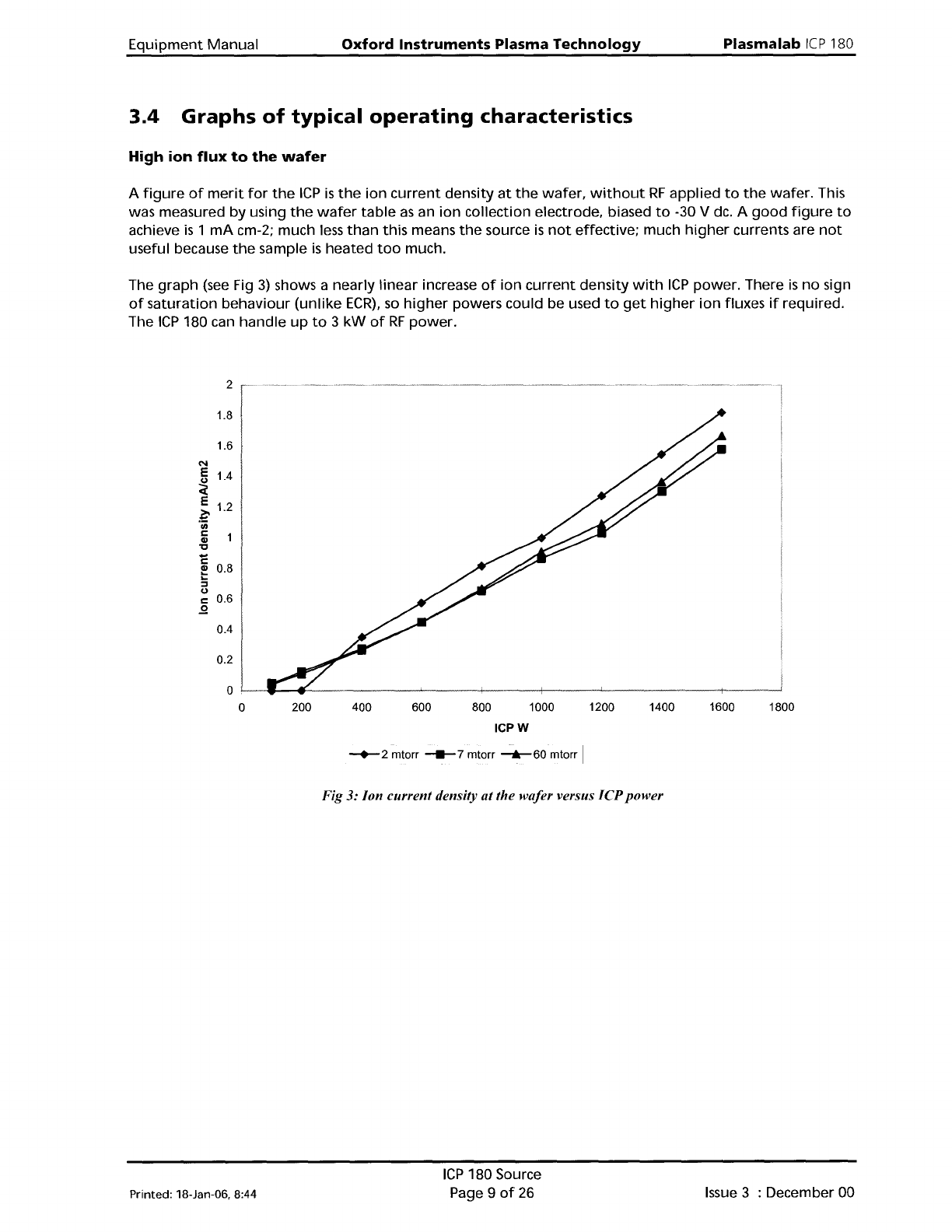
High
ion
flux
to
the
wafer
A
figure
of
merit
for
the
ICP
is
the
ion
current
density
at
the
wafer,
without
RF
applied
to
the
wafer.
This
was measured by using
the
wafer
table
as
an
ion
collection electrode, biased
to
-30 V dc. A
good
figure
to
achieve
is
1
mA
cm-2; much
less
than
this means
the
source
is
not
effective; much
higher
currents are
not
useful because
the
sample
is
heated
too
much.
The
graph
(see
Fig
3)
shows a nearly
linear
increase
of
ion
current
density
with
ICP
power. There
is
no
sign
of
saturation
behaviour
(unlike
ECR),
so
higher
powers could be used
to
get
higher
ion
fluxes
if
reqUired.
The
ICP
180 can
handle
up
to
3
kW
of
RF
power.
1.8
1.6
N
E 1.4
~
E
~ 1.2
'iii
r::
Gl
'C
1:
~
0.8
...
:::l
CJ
r::
0.6
..!2
0.4
0.2
1800160014001200
800 1000
ICPW
600400200
0l--~-4--------~---4----+----l..----------+------i
o
-+-
2 mtorr
_7
mtorr
-.-
60 mtorr I
Fig
3:
Jon current density at the wafer versus JCP power
Printed: 18-Jan-06. 8:44
ICP
180 Source
Page 9
of
26
Issue
3 : December 00
Plasma
lab
Ie
P180
Operating
window
Oxford
Instruments Plasma Technology Equipment Manual
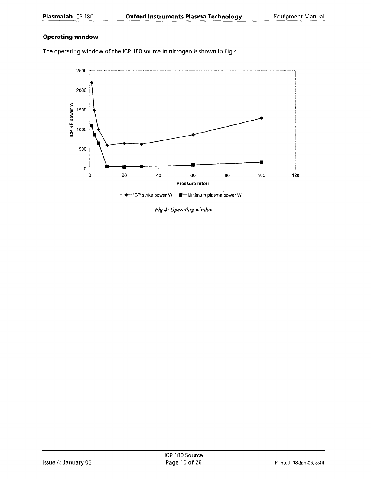
The
operating
window
of
the
ICP
180 source in
nitrogen
is
shown in Fig
4.
2500
2000
:!:
..
1500
Gl
~
0
Q.
U.
~
1000
ll.
!d
500
Pressure
mtorr
i
-+-ICP
strike power W _ Minimum plasma power W
Fig 4: Operating window
Issue
4:
January 06
ICP
180 Source
Page 10
of
26
Printed: 18-Jan-06, 8:44