Oxford-100-Manual.pdf - 第254页
Plasma lab ICP 180 Oxford Instruments Plasma Technology Equipment Manual d) Follow the procedure in Section 7 (Troubleshooting) for improving the quality of the match. e) Vary the pressure across the 1 to 5 Pa range. It …
Equipment
Manual
Oxford
Instruments
Plasma
Technology
Plasma
lab
ICP
180
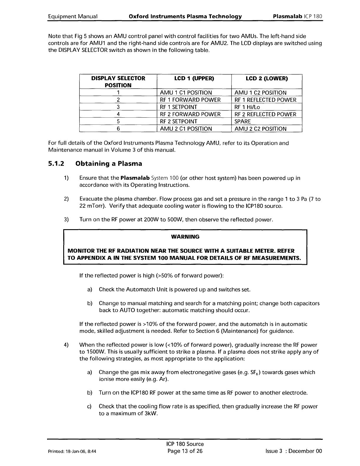
Note
that
Fig 5 shows an
AMU
control
panel
with
control
facilities
for
two
AMUs. The
left-hand
side
controls are
for
AMU1 and
the
right-hand
side controls are
for
AMU2. The
LCD
displays are switched using
the
DISPLAY
SELECTOR
switch
as
shown in
the
following
table.
DISPLAY
SELECTOR
LCD 1 (UPPER)
LCD 2 (LOWER)
POSITION
1
AMU
1
C1
POSITION
AMU
1
C2
POSITION
2
RF
1 FORWARD
POWER
RF
1
REFLECTED
POWER
3
RF
1
SETPOINT
RF
1
Hillo
4
RF
2 FORWARD
POWER
RF
2
REFLECTED
POWER
5
RF
2
SETPOINT
SPARE
6
AMU
2
C1
POSITION
AMU
2
C2
POSITION
For
full
details
of
the
Oxford
Instruments Plasma Technology
AMU,
refer
to
its
Operation
and
Maintenance
manual in
Volume
3
of
this manual.
5.1.2
Obtaining
a Plasma
1)
Ensure
that
the
Plasma
lab
System
100 (or
other
host system) has been
powered
up
in
accordance
with
its
Operating
Instructions.
2)
Evacuate
the
plasma chamber. Flow process gas and set a pressure
in
the
range 1
to
3
Pa
(7
to
22
mTorr).
Verify
that
adequate
cooling
water
is
flowing
to
the
ICP180 source.
3)
Turn on
the
RF
power
at
200W
to
500W,
then
observe
the
reflected power.
WARNING
MONITOR THE
RF
RADIATION NEAR
THE
SOURCE WITH A SUITABLE METER.
REFER
TO APPENDIX A
IN
THE
SYSTEM
100
MANUAL
FOR DETAILS
OF
RF
MEASUREMENTS.
If
the
reflected
power
is
high
(>50%
of
forward
power):
a)
Check
the
Automatch
Unit
is
powered
up
and switches set.
b) Change
to
manual
matching
and search
for
a
matching
point;
change
both
capacitors
back
to
AUTO
together:
automatic
matching
should occur.
If
the
reflected
power
is
>10%
of
the
forward
power, and
the
automatch
is
in
automatic
mode, skilled
adjustment
is
needed. Refer
to
Section 6 (Maintenance)
for
guidance.
4)
When
the
reflected
power
is
low
«10%
of
forward
power),
gradually
increase
the
RF
power
to
1500W. This
is
usually
sufficient
to
strike a plasma.
If
a plasma does
not
strike apply any
of
the
following
strategies,
as
most
appropriate
to
the
application:
a)
Change
the
gas
mix
away
from
electronegative
gases (e.g.
SF
6
)
towards
gases
which
ionise
more
easily (e.g. Ar).
b) Turn
on
the
ICP180
RF
power
at
the
same
time
as
RF
power
to
another
electrode.
c)
Check
that
the
cooling
flow
rate
is
as
specified,
then
gradually
increase
the
RF
power
to
a
maximum
of
3kW.
Printed: l8-Jan-D6, 8:44
ICP
180 Source
Page 13
of
26
Issue
3 : December 00
Plasma
lab
ICP
180
Oxford
Instruments Plasma Technology
Equipment
Manual
d)
Follow
the
procedure
in
Section 7 (Troubleshooting)
for
improving
the
quality
of
the
match.
e)
Vary
the
pressure across
the
1
to
5
Pa
range.
It
is
usually possible
to
start
the
plasma
directly
at
process conditions
of
interest. However,
it
is
difficult
to
sustain a plasma
at
low
RF
power
(<300W).
Issue
4:
January 06
ICP
180 Source
Page 14
of
26
Printed: 18-Jan-06, 8:44
Equipment
Manual
Oxford
Instruments Plasma Technology
WARNING
Plasma
lab
ICP
180
BEFORE
PROCEEDING WITH
ANY
MAINTENANCE WORK, READ SECTION 1 - HEALTH
AND
SAFETY.
6.
Maintenance
6.1
Maintenance
schedule
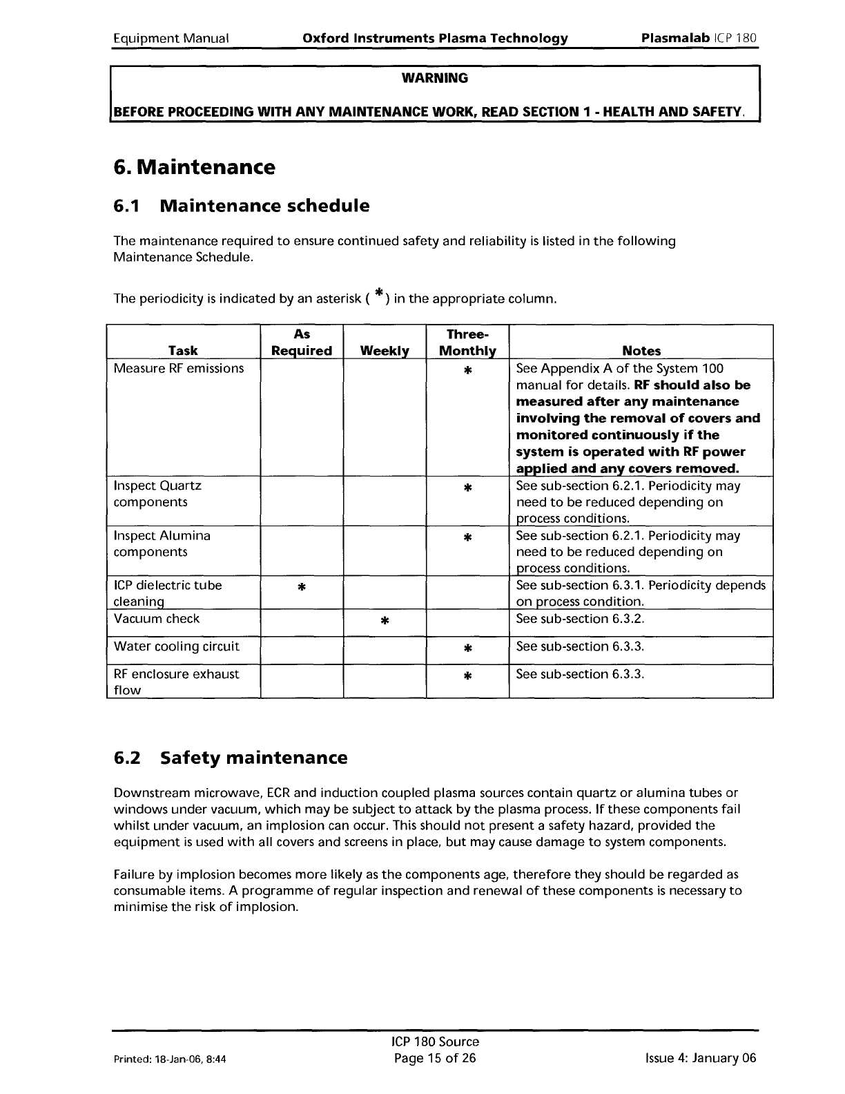
The maintenance
required
to
ensure
continued
safety and
reliability
is
listed in
the
following
Maintenance
Schedule.
The
periodicity
is
indicated by an asterisk (
*)
in
the
appropriate
column.
As
Three-
Task Required
Weekly
Monthly
Notes
Measure
RF
emissions
*
See
Appendix
A
of
the
System 100
manual
for
details.
RF
should also be
measured
after
any
maintenance
involving
the
removal
of
covers
and
monitored
continuously
if
the
system
is
operated
with
RF
power
applied
and
any
covers
removed.
Inspect
Quartz
*
See
sub-section 6.2.1. Periodicity may
components
need
to
be reduced
depending
on
process conditions.
Inspect
Alumina
*
See
sub-section 6.2.1. Periodicity may
components need
to
be reduced
depending
on
process conditions.
ICP
dielectric
tube
*
See
sub-section 6.3.1. Periodicity depends
cleaninq
on
process
condition.
Vacuum check
*
See
sub-section 6.3.2.
Water
cooling circuit
*
See
sub-section 6.3.3.
RF
enclosure exhaust
*
See
sub-section 6.3.3.
flow
6.2
Safety
maintenance
Downstream microwave,
ECR
and
induction
coupled plasma sources contain
quartz
or
alumina
tubes
or
windows
under
vacuum,
which
may be subject
to
attack
by
the
plasma process.
If
these components fail
whilst
under
vacuum, an implosion can occur. This should
not
present a safety hazard, provided
the
equipment
is
used
with
all covers and screens in place,
but
may cause damage
to
system components.
Failure
by
implosion becomes
more
likely
as
the
components age,
therefore
they
should be regarded
as
consumable items. A
programme
of
regular
inspection and renewal
of
these components
is
necessary
to
minimise
the
risk
of
implosion.
Printed: 18-Jan-DB, 8:44
ICP
180 Source
Page 15
of
26
Issue
4:
January 06