Oxford-100-Manual.pdf - 第269页
System Manual Oxford Instruments Plasma Technology All OIPT Systems 1. Health and Safety For Health and Safety aspects of operating and maintaining the Oxford Instruments Plasma Technology Automatch Unit, refer to Sectio…
All
OIPT Systems
Contents
Oxford
Instruments
Plasma
Technology
System
Manual
1.
Health
and
Safety
3
2.
Description
3
2.1
Introduction
3
2.2
Major
components 4
2.2.1
Automatch
control
panel 4
2.3
Matching
component
layouts 5
2.4
Sense
and
control
PCB
7
3. Test
and
setting
up
8
3.1 Overview 8
3.2
Procedure 9
4.
Operator
adjustment
13
4.1
DC
bias I Peak-to-peak switch setting 13
5.
Operation
13
6.
Troubleshooting
15
6.1 Fault diagnosis
chart
15
6.1.1
Amplifier
gain
adjustment
16
6.1.2 Drive
motor
shaft
to
capacitor spindle
alignment
17
6.2
Link Settings 18
6.3
Changing
the
RF
components 19
6.4
Adjustment
of
capacitor
park
positions 20
7. OIPT
locations
worldwide
20
Fig
1:
The
Oxford
Instruments Plasma Technology
automatch
unit
3
Fig
2:
Typical
AMU
control
panel 4
Fig
3:
Matching
component
layouts 6
Fig
4:
Sense
and
control
PCB
layout
7
Fig
5:
Capacitor shafts
rotation
direction
10
Fig
6:
Component
locations
11
Fig
7:
LK102 and
LK2
settings 16
Issue
6:
February
05
OIPT
Automatch
Unit
Page 2
of
20
Printed: 5-Jan-06, 8:03
System Manual
Oxford
Instruments
Plasma
Technology
All
OIPT Systems
1.
Health
and
Safety
For Health and Safety aspects
of
operating
and
maintaining
the
Oxford
Instruments Plasma
Technology
Automatch
Unit,
refer
to
Section 1 - Health and Safety
of
your
Plasma
lab
or
lonfab
system manual.
2. Description
2.1
Introduction
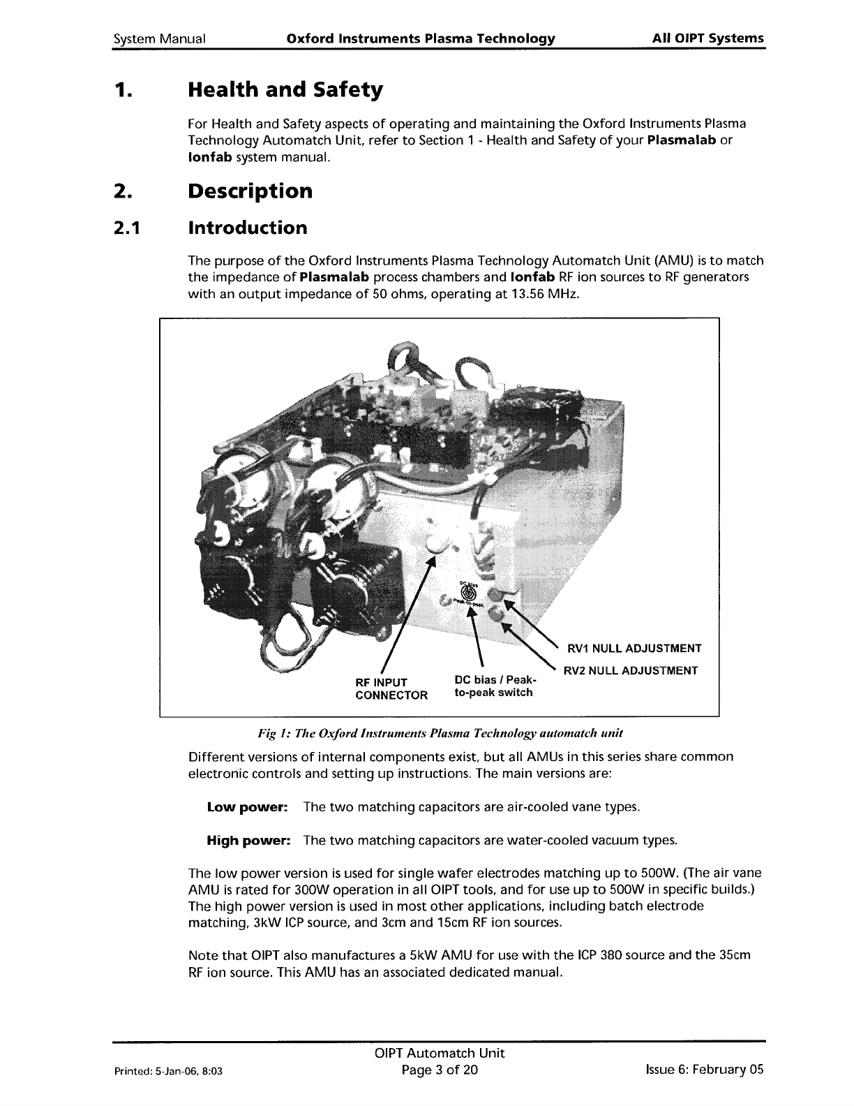
The purpose
of
the
Oxford
Instruments Plasma Technology
Automatch
Unit
(AMU)
is
to
match
the
impedance
of
Plasma
lab
process chambers and
lonfab
RF
ion sources
to
RF
generators
with
an
output
impedance
of
50 ohms,
operating
at
13.56 MHz.
RF
INPUT
CONNECTOR
DC
bias
I Peak-
to-peak
switch
RV1
NULL ADJUSTMENT
RV2
NULL
ADJUSTMENT
Fig
1:
The OxfordInstruments Plasma Technology automatch
unit
Different
versions
of
internal components exist,
but
all AMUs in this series share common
electronic controls and
setting
up
instructions. The main versions are:
Low
power:
The
two
matching capacitors are air-cooled vane types.
High
power:
The
two
matching capacitors are water-cooled vacuum types.
The
low
power
version
is
used
for
single
wafer
electrodes matching
up
to
500W. (The air vane
AMU
is
rated
for
300W
operation
in all
OIPT
tools, and
for
use
up
to
500W in specific builds.)
The
high
power
version
is
used in most
other
applications, including batch electrode
matching,
3kW
ICP
source, and 3cm and 15cm
RF
ion sources.
Note
that
OIPT
also manufactures a
5kW
AMU
for
use
with
the
ICP
380 source and
the
35cm
RF
ion source. This
AMU
has an associated dedicated manual.
Printed: 5-Jan-06, 8:03
OIPT
Automatch
Unit
Page 3
of
20
Issue
6:
February
05
All
OIPT
Systems
Oxford
Instruments
Plasma
Technology
System
Manual
2.2
Major
components
The
AMU
comprises:
a)
an
input
section
with
a
type
N coaxial connector, and a coupler
giving
'out
of
match'
error
signals
when
the
reflected
power
is
greater
than
1%
of
the
forward
power.
b) an
RF
section
containing
two
motor-driven
variable capacitors,
together
with
a coil
where
necessary.
c)
a
DC
bias / Peak
to
peak, set by local switch, signal path. (Only
fitted
to
AMUs used
for
matching
to
a
powered
wafer
table.)
d) an electronic
control
board,
which
uses
the
error
signals
to
drive
the
variable
capacitors
towards
match.
e)
a manual
drive
panel
with
capacitor position readings,
for
manual adjustments.
2.2.1
Automatch
control
panel
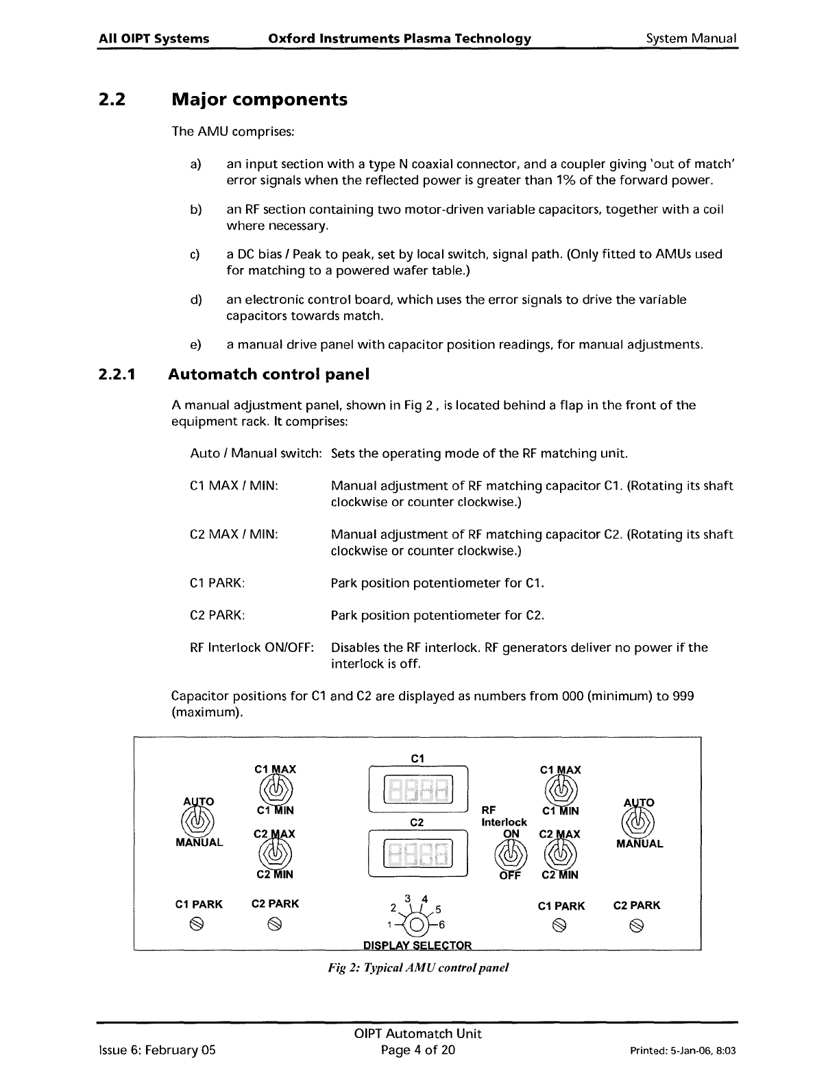
A manual
adjustment
panel, shown in Fig 2 ,
is
located
behind
a
flap
in
the
front
of
the
equipment
rack.
It
comprises:
Auto
/
Manual
switch: Sets
the
operating
mode
of
the
RF
matching
unit.
C1
MAX
/ MIN:
Manual
adjustment
of
RF
matching
capacitor
C1.
(Rotating its
shaft
clockwise
or
counter
clockwise.)
C2
MAX
/ MIN:
Manual
adjustment
of
RF
matching
capacitor
C2.
(Rotating its
shaft
clockwise
or
counter
clockwise.)
C1
PARK:
Park position
potentiometer
for
C1.
C2
PARK:
Park
position
potentiometer
for
C2.
RF
Interlock
ON/OFF: Disables
the
RF
interlock.
RF
generators deliver
no
power
if
the
interlock
is
off.
Capacitor positions
for
C1
and
C2
are displayed
as
numbers
from
000 (minimum)
to
999
(maximum).
C1
J?
J?
i)
i)
C1
IN
RF
C1
IN
C2
Interlock
CI
ON
CI
MANUAL
~
MANUAL
C2
IN
C2
IN
C1
PARK
C2
PARK
C1
PARK
C2
PARK
e e
e
e
DI
Fig 2: Typical
AMU
control
panel
Issue
6:
February 05
OIPT
Automatch
Unit
Page 4
of
20
Printed: 5-Jan-06, 8:03