Oxford-100-Manual.pdf - 第271页
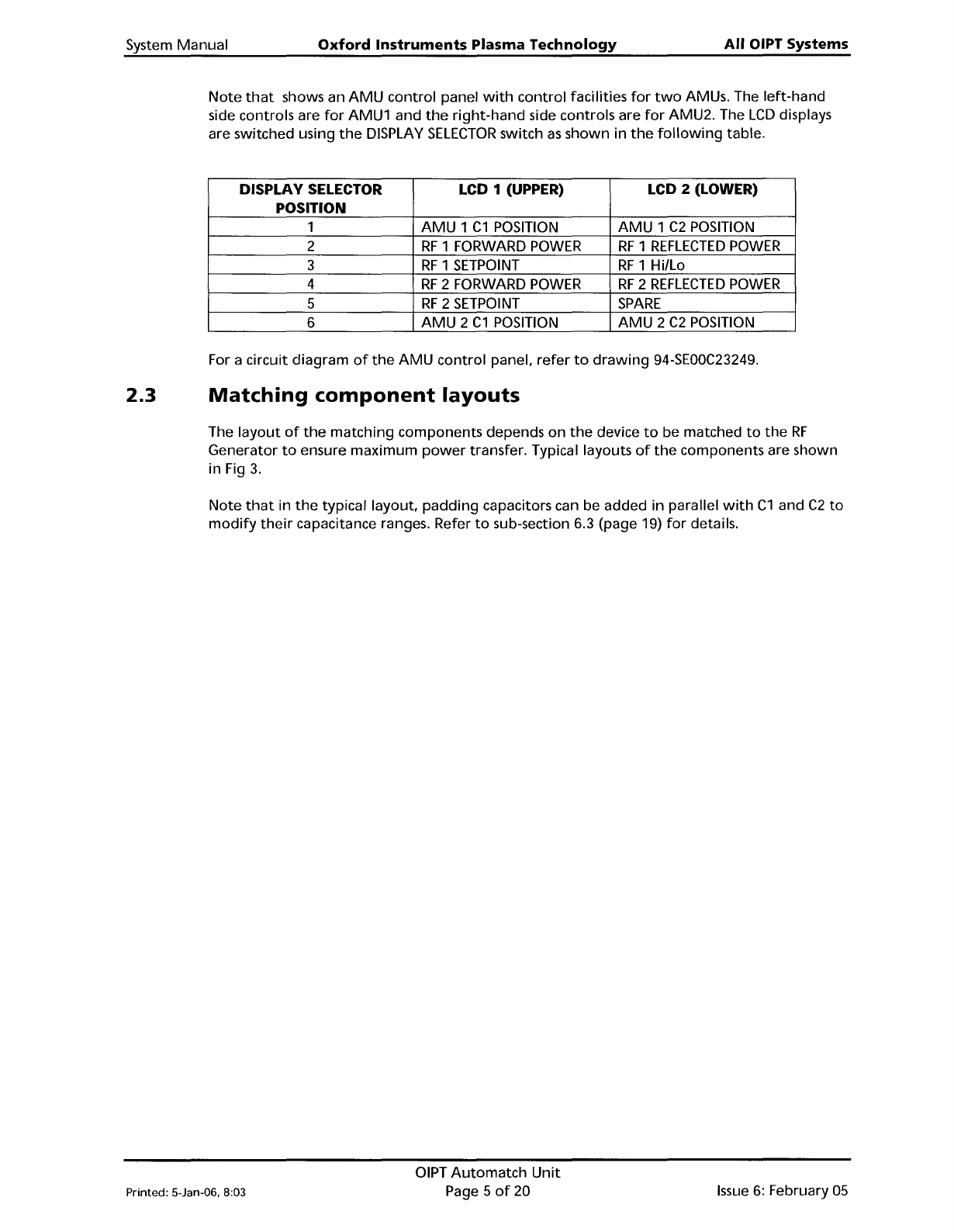
System Manual Oxford Instruments Plasma Technology All OIPT Systems Note that shows an AMU control panel with control facilities for two AMUs. The left-hand side controls are for AMU1 and the right-hand side controls are…
All
OIPT
Systems
Oxford
Instruments
Plasma
Technology
System
Manual
2.2
Major
components
The
AMU
comprises:
a)
an
input
section
with
a
type
N coaxial connector, and a coupler
giving
'out
of
match'
error
signals
when
the
reflected
power
is
greater
than
1%
of
the
forward
power.
b) an
RF
section
containing
two
motor-driven
variable capacitors,
together
with
a coil
where
necessary.
c)
a
DC
bias / Peak
to
peak, set by local switch, signal path. (Only
fitted
to
AMUs used
for
matching
to
a
powered
wafer
table.)
d) an electronic
control
board,
which
uses
the
error
signals
to
drive
the
variable
capacitors
towards
match.
e)
a manual
drive
panel
with
capacitor position readings,
for
manual adjustments.
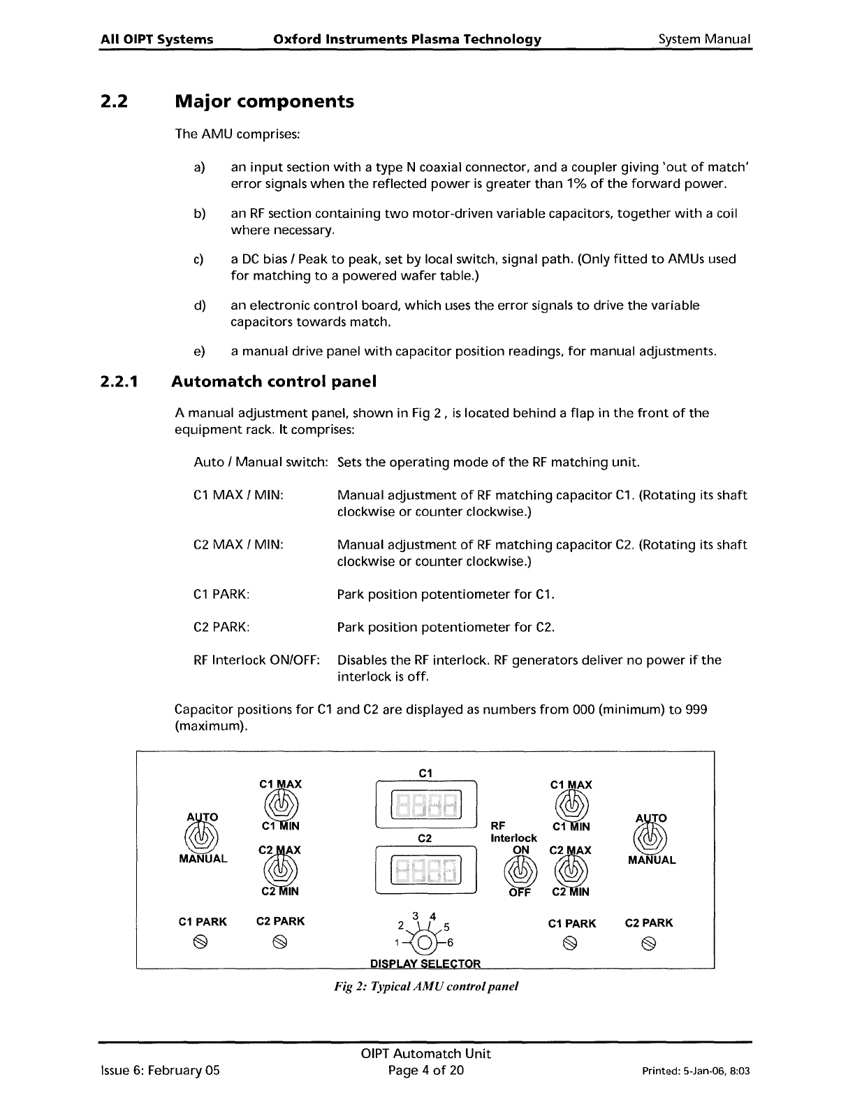
2.2.1
Automatch
control
panel
A manual
adjustment
panel, shown in Fig 2 ,
is
located
behind
a
flap
in
the
front
of
the
equipment
rack.
It
comprises:
Auto
/
Manual
switch: Sets
the
operating
mode
of
the
RF
matching
unit.
C1
MAX
/ MIN:
Manual
adjustment
of
RF
matching
capacitor
C1.
(Rotating its
shaft
clockwise
or
counter
clockwise.)
C2
MAX
/ MIN:
Manual
adjustment
of
RF
matching
capacitor
C2.
(Rotating its
shaft
clockwise
or
counter
clockwise.)
C1
PARK:
Park position
potentiometer
for
C1.
C2
PARK:
Park
position
potentiometer
for
C2.
RF
Interlock
ON/OFF: Disables
the
RF
interlock.
RF
generators deliver
no
power
if
the
interlock
is
off.
Capacitor positions
for
C1
and
C2
are displayed
as
numbers
from
000 (minimum)
to
999
(maximum).
C1
J?
J?
i)
i)
C1
IN
RF
C1
IN
C2
Interlock
CI
ON
CI
MANUAL
~
MANUAL
C2
IN
C2
IN
C1
PARK
C2
PARK
C1
PARK
C2
PARK
e e
e
e
DI
Fig 2: Typical
AMU
control
panel
Issue
6:
February 05
OIPT
Automatch
Unit
Page 4
of
20
Printed: 5-Jan-06, 8:03
System
Manual
Oxford
Instruments
Plasma
Technology
All
OIPT Systems
Note
that
shows an
AMU
control
panel
with
control
facilities
for
two
AMUs. The
left-hand
side controls are
for
AMU1 and
the
right-hand
side controls are
for
AMU2. The
LCD
displays
are switched using
the
DISPLAY
SELECTOR
switch
as
shown
in
the
following
table.
DISPLAY SELECTOR LCD 1 (UPPER)
LCD 2 (LOWER)
POSITION
1
AMU
1
C1
POSITION
AMU
1
C2
POSITION
2
RF
1 FORWARD
POWER
RF
1
REFLECTED
POWER
3
RF
1
SETPOINT
RF
1 Hilla
4
RF
2 FORWARD
POWER
RF
2
REFLECTED
POWER
5
RF
2
SETPOINT
SPARE
6
AMU
2
C1
POSITION
AMU
2
C2
POSITION
For a circuit
diagram
of
the
AMU
control
panel.
refer
to
drawing
94-SEOOC23249.
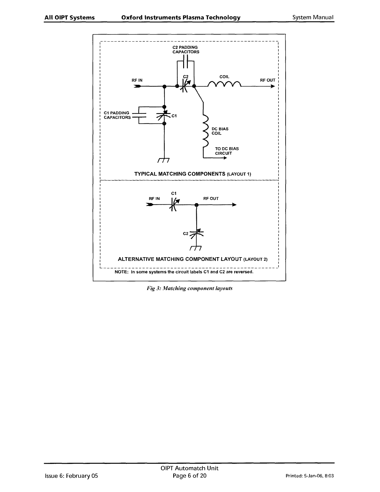
2.3
Matching
component
layouts
The
layout
of
the
matching
components depends
on
the
device
to
be matched
to
the
RF
Generator
to
ensure
maximum
power
transfer. Typical layouts
of
the
components are shown
in Fig
3.
Note
that
in
the
typical layout,
padding
capacitors can be added in parallel
with
C1
and
C2
to
modify
their
capacitance ranges. Refer
to
sub-section 6.3 (page 19)
for
details.
Printed: 5-Jan-06, 8:03
OIPT
Automatch
Unit
Page 5
of
20
Issue
6:
February
05
All
OIPT
Systems
Oxford
Instruments
Plasma
Technology
System
Manual
RFOUT
TO
DC
BIAS
CIRCUIT
C2 PADDING
CAPACITORS
C1
TYPICAL MATCHING COMPONENTS (LAYOUT 1)
RF
IN
~-------------------------------------------------
I
I
I
I
I
I
I
I
C1
PADDING
: CAPACITORS
I
I
I
I
I
I
I
I
I
I
I
I
I
I
I
I
I
RFOUT
C2
C1
RFIN
I
I
I
I
I
I
I
I
I
I
I
I
I
I
I
I
I
I
I
I
I
I
: ALTERNATIVE MATCHING COMPONENT LAYOUT (LAYOUT 2) I
I I
L
1
NOTE: In
some
systems
the
circuit
labels
C1
and
C2 are reversed.
Fig
3:
Matching component layouts
Issue
6:
February 05
OIPT
Automatch
Unit
Page 6
of
20
Printed: 5-Jan-06. 8:03