Oxford-100-Manual.pdf - 第273页
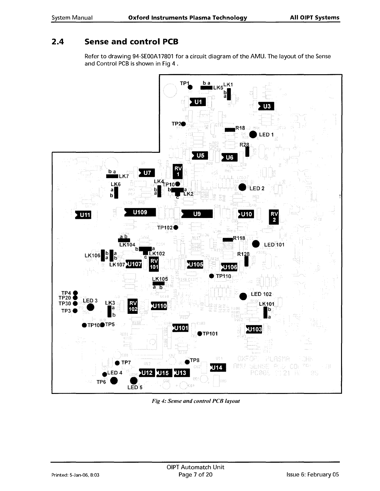
System Manual Oxford Instruments Plasma Technology All OIPT Systems 2.4 Sense and control PCB Refer to drawing 94-SEOOA 17801 for a circuit diagram of the AMU. The layout of the Sense and Control PCB is shown in Fig 4 . …
All
OIPT
Systems
Oxford
Instruments
Plasma
Technology
System
Manual
RFOUT
TO
DC
BIAS
CIRCUIT
C2 PADDING
CAPACITORS
C1
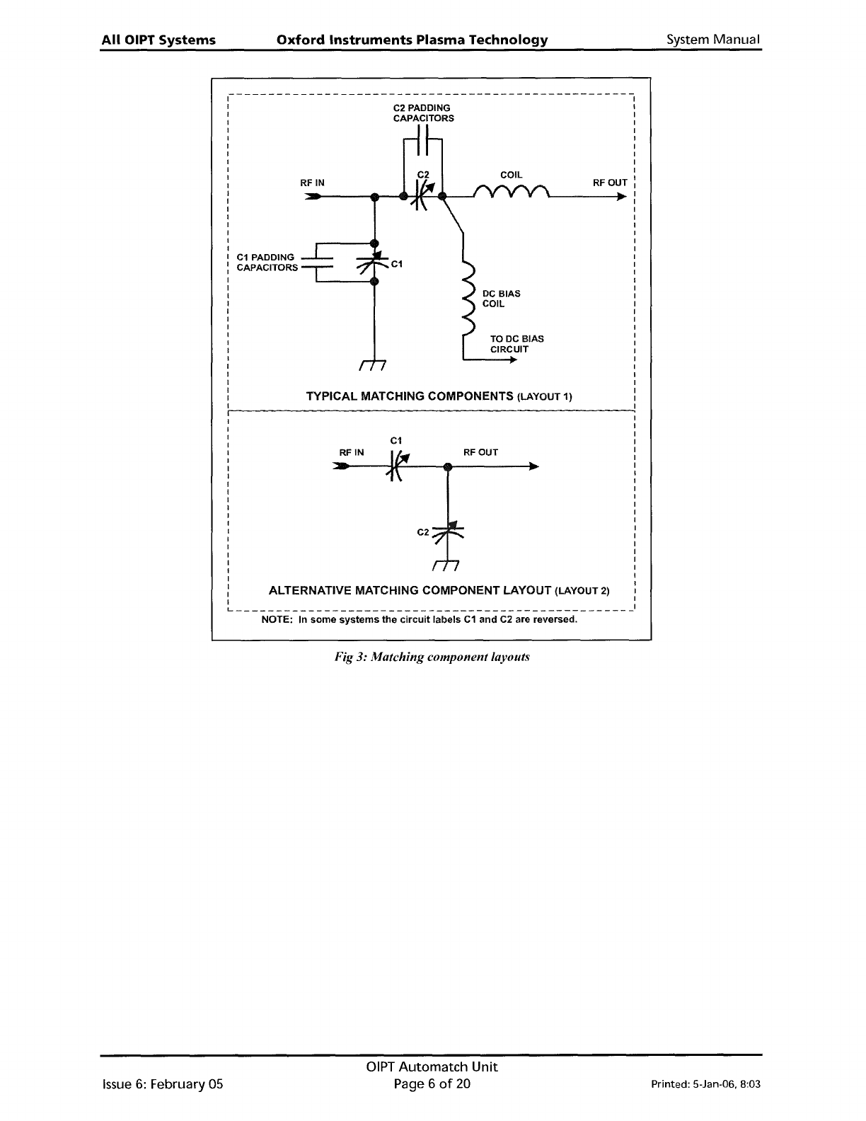
TYPICAL MATCHING COMPONENTS (LAYOUT 1)
RF
IN
~-------------------------------------------------
I
I
I
I
I
I
I
I
C1
PADDING
: CAPACITORS
I
I
I
I
I
I
I
I
I
I
I
I
I
I
I
I
I
RFOUT
C2
C1
RFIN
I
I
I
I
I
I
I
I
I
I
I
I
I
I
I
I
I
I
I
I
I
I
: ALTERNATIVE MATCHING COMPONENT LAYOUT (LAYOUT 2) I
I I
L
1
NOTE: In
some
systems
the
circuit
labels
C1
and
C2 are reversed.
Fig
3:
Matching component layouts
Issue
6:
February 05
OIPT
Automatch
Unit
Page 6
of
20
Printed: 5-Jan-06. 8:03
System Manual
Oxford
Instruments
Plasma
Technology
All
OIPT Systems
2.4
Sense
and
control
PCB
Refer
to
drawing
94-SEOOA
17801
for
a circuit diagram
of
the
AMU. The
layout
of
the
Sense
and Control
PCB
is
shown in Fig 4 .
TP.
..1.ED1
ba
_LK7
LK6
~I
2
Ii
Iii.
LK104
b_a
LK1061bla
-.LK102
a b
em
LK107211'!1
Iii
LK105
".
• LED 102
TP41
TP20
TP30e
TP3e
LED 3
•
LK3
I~
• LED
101
eTP101
4i\mDmI:mI
LED 5
eTP7
e
LED4
TP6.
Fig 4: Sense
and
control PCB layout
Printed: 5-Jan-06, 8:03
DIPT
Automatch
Unit
Page 7
of
20
Issue
6:
February
05
All
OIPT Systems
Oxford
Instruments
Plasma
Technology
System Manual
3. Test
and
setting
up
WARNING
HAZARDOUS
RF
VOLTAGE·
CONTACT CAN CAUSE DEATH,
SEVERE
INJURY
OR BURNS.
ANY
WORK REQUIRING
THE
REMOVAL
OF
COVERS
OR
PANELS MUST
ONLY
BE
PERFORMED BY AUTHORISED PERSONNEL WHO
ARE
AWARE
OF
THE HAZARDS INVOLVED.
NOTE:
Detailed test instructions are contained in
Oxford
Instruments Plasma Technology
Work
Instruction No.
39.
The
following
is
a summary
for
the
benefit
of
skilled service
engineers.
It
should
not
be necessary
for
operators
to
perform
these setting
up
operations.
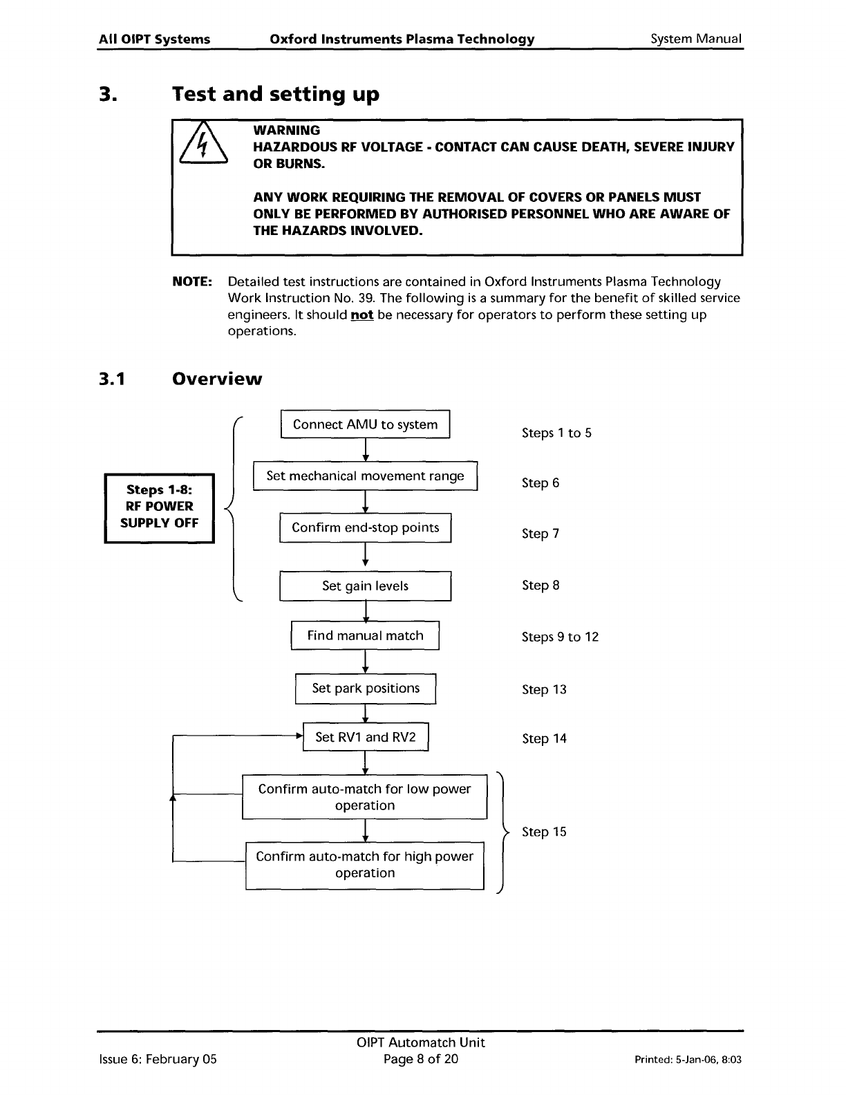
3.1
Overview
Steps 1-8:
RF
POWER
SUPPLY
OFF
Connect
AMU
to
system
Set mechanical
movement
range
Confirm
end-stop points
Steps 1
to
5
Step 6
Step 7
I
Set gain levels
1
I
Find manual match
I
!
I
Set
park
positions
I
!
I
Set
RV1
and
RV2
I
I
!
Confirm
auto-match
for
low
power
operation
!
Confirm
auto-match
for
high
power
operation
Step 8
Steps 9
to
12
Step
13
Step 14
Step
15
Issue
6:
February 05
OIPT
Automatch
Unit
Page 8
of
20
Printed: 5-Jan-06. 8:03