Oxford-100-Manual.pdf - 第275页
System Manual 3.2 Procedure Oxford Instruments Plasma Technology All OIPT Systems WARNING HAZARDOUS RF VOLTAGE· CONTACT CAN CAUSE DEATH, SEVERE INJURY OR BURNS. ENSURE THAT THE RF SUPPLY IS SWITCHED OFF WHILE CARRYING OU…
All
OIPT Systems
Oxford
Instruments
Plasma
Technology
System Manual
3. Test
and
setting
up
WARNING
HAZARDOUS
RF
VOLTAGE·
CONTACT CAN CAUSE DEATH,
SEVERE
INJURY
OR BURNS.
ANY
WORK REQUIRING
THE
REMOVAL
OF
COVERS
OR
PANELS MUST
ONLY
BE
PERFORMED BY AUTHORISED PERSONNEL WHO
ARE
AWARE
OF
THE HAZARDS INVOLVED.
NOTE:
Detailed test instructions are contained in
Oxford
Instruments Plasma Technology
Work
Instruction No.
39.
The
following
is
a summary
for
the
benefit
of
skilled service
engineers.
It
should
not
be necessary
for
operators
to
perform
these setting
up
operations.
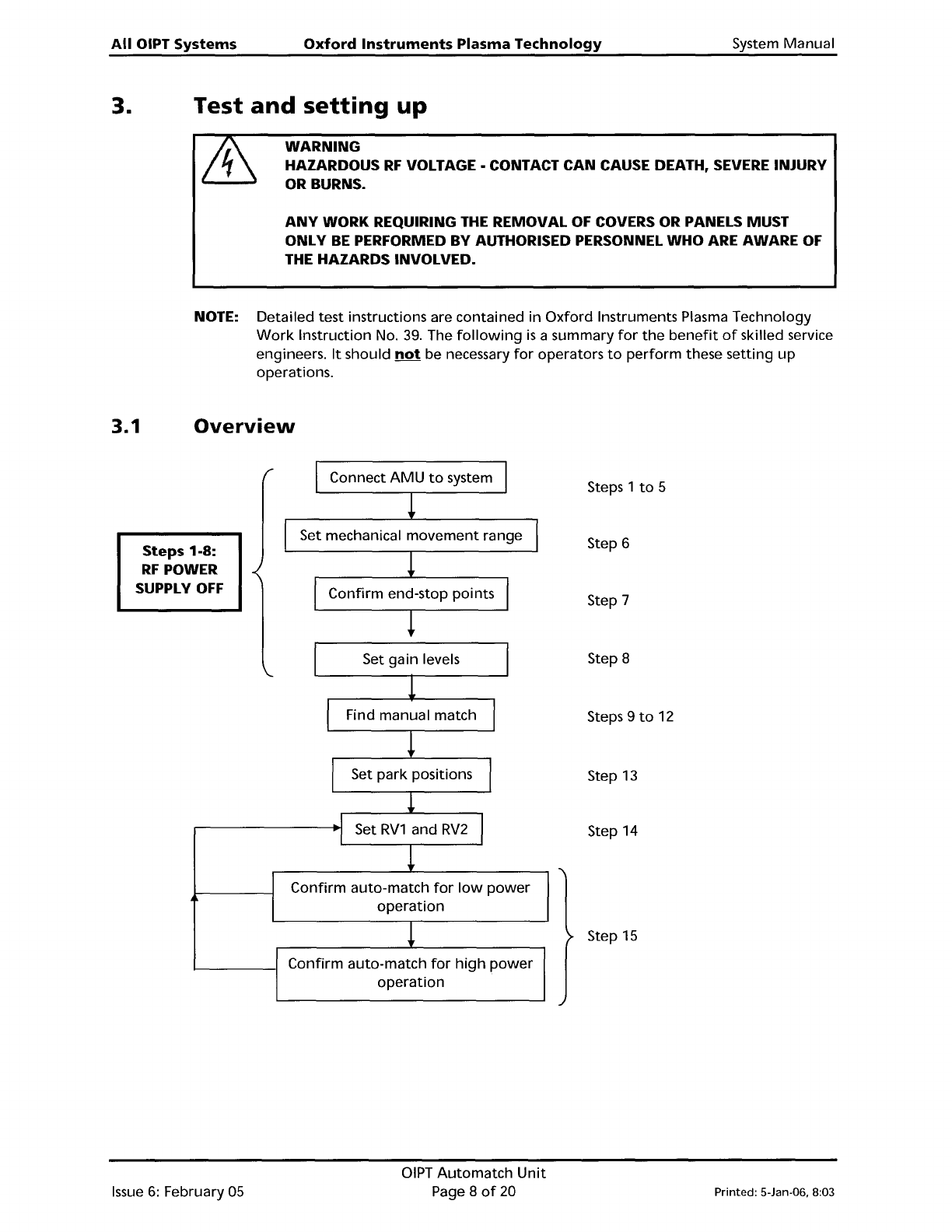
3.1
Overview
Steps 1-8:
RF
POWER
SUPPLY
OFF
Connect
AMU
to
system
Set mechanical
movement
range
Confirm
end-stop points
Steps 1
to
5
Step 6
Step 7
I
Set gain levels
1
I
Find manual match
I
!
I
Set
park
positions
I
!
I
Set
RV1
and
RV2
I
I
!
Confirm
auto-match
for
low
power
operation
!
Confirm
auto-match
for
high
power
operation
Step 8
Steps 9
to
12
Step
13
Step 14
Step
15
Issue
6:
February 05
OIPT
Automatch
Unit
Page 8
of
20
Printed: 5-Jan-06. 8:03
System
Manual
3.2
Procedure
Oxford
Instruments
Plasma
Technology
All OIPT Systems
WARNING
HAZARDOUS
RF
VOLTAGE·
CONTACT CAN CAUSE DEATH,
SEVERE
INJURY
OR
BURNS.
ENSURE THAT
THE
RF
SUPPLY IS SWITCHED
OFF
WHILE CARRYING OUT
STEPS
1 TO
8.
1)
Connect
the
AMU
to
the
system.
Make
a
good
earth
bond
between
the
vacuum
chamber and
the
AMU
chassis.
2) Connect
the
output
strap
to
the
plasma electrode
with
at
least a 25
mm
wide
copper
strap,
with
at
least
10
mm
clearance
between
the
live strap and any earthed part.
3)
Confirm
the
polarity
and
voltage
of
the
dc
power
source
before
connecting
to
the
Sense and
Control
PCB:
JP7
pin
1
JP7
pin
2
+24 Vdc
OV
4)
Ensure
the
ventilation
fans are all
pulling
air
out
of
the
automatch
case
and check
the
system
cooling
is
turned
on. For sense
board
cooling, check
one
fan
is
pulling
air
out
and
one
is
pulling
air in
to
the
sense board section.
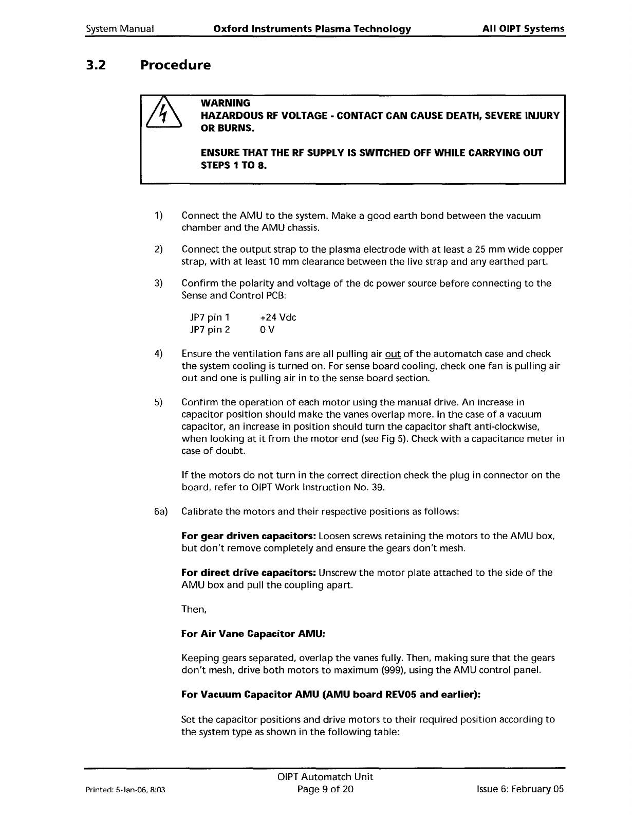
5)
Confirm
the
operation
of
each
motor
using
the
manual drive.
An
increase in
capacitor
position
should
make
the
vanes overlap more. In
the
case
of
a vacuum
capacitor, an increase in
position
should
turn
the
capacitor
shaft
anti-clockwise,
when
looking
at
it
from
the
motor
end
(see
Fig
5).
Check
with
a capacitance
meter
in
case
of
doubt.
If
the
motors
do
not
turn
in
the
correct
direction
check
the
plug
in connector on
the
board,
refer
to
DIPT
Work
Instruction No.
39.
6a) Calibrate
the
motors
and
their
respective positions
as
follows:
For
gear
driven
capacitors: Loosen screws
retaining
the
motors
to
the
AMU
box,
but
don't
remove
completely
and ensure
the
gears
don't
mesh.
For
direct
drive
capacitors: Unscrew
the
motor
plate
attached
to
the
side
of
the
AMU
box
and pull
the
coupling
apart.
Then,
For
Air
Vane
Capacitor
AMU:
Keeping gears separated, overlap
the
vanes fully. Then,
making
sure
that
the
gears
don't
mesh,
drive
both
motors
to
maximum
(999), using
the
AMU
control
panel.
For
Vacuum
Capacitor
AMU
(AMU
board
REV05
and
earlier):
Set
the
capacitor positions and drive
motors
to
their
required position according
to
the
system
type
as
shown
in
the
following
table:
Printed: 5-Jan-06, 8:03
DIPT
Automatch
Unit
Page 9
of
20
Issue
6:
February
05
All
OIPT Systems
Oxford
Instruments
Plasma
Technology
System Manual
System
Set
C1
Then
Drive
SetC2
Then
Drive
Type
to
move
C1
to
Move
C2
in
Motor
in
Motor
to
to
RIE/DP
Maximum
1
turn
Maximum
Maximum
1
turn
Maximum
(999) (999)
ICP180
Maximum
1
turn
Maximum
Minimum
1
turn
Minimum
(999) (000)
Ion
Beam
Minimum
1
turn
Minimum Minimum
1
turn
Minimum
(000) (000)
ICP
380
Maximum
1
turn
Maximum Maximum
7 Turns
Maximum
(999) (999)
To
find
the
minimum
position,
turn
the
capacitor
shaft
in
the
direction
of
the
arrow,
shown in Fig
5.
To
find
the
maximum
position,
turn
the
capacitor
shaft
opposite
to
the
direction
of
the
arrow
in Fig
5.
At
the
minimum
position,
the
shaft
becomes
stiff;
at
the
maximum
position,
the
shaft
becomes loose.
Do
not
try
to
turn
the
shaft
past
these
points.
If
when
turning
the
capacitor
to
the
maximum
position,
the
shaft
becomes loose,
turn
the
shaft
back in
until
it
just
begins
to
bite, this
is
the
maximum position.
Fig 5: Capacitor shafts rotation direction
For
Vacuum
Capacitor
AMU
(AMU
board
with
capacitor
range
mod.):
(Applies
to
all
system
types)
Rotate
the
vacuum capacitor
shaft
clockwise
as
you
look
at
it
from
the
motor
end
(see
Fig
5)
until
the
shaft
just
becomes stiff, and
then
turn
in
half
a
turn.
Making
sure
the
motors
don't
mesh,
drive
both
motors
to
minimum
(000).
6b) For
gear
driven
capacitors: Re-mesh
the
gears and
tighten
motor
retaining
screws, ensuring
that
the
motor
and capacitor positions
don't
move.
For
direct
drive
capacitors: Loosen
the
coupling
clamp screw on
the
capacitor
side,
turn
the
coupling
on
the
capacitor side
until
it
lines
up
wit
that
on
the
motor
side ensuring
neither
the
capacitor
nor
the
motor
change
position
at
any time. Clip
the
coupling
together
and
tighten
the
clamp screw. Then re-attach
the
motor
plate.
7)
Confirm
the
'end
of
range' stop functions using
the
manual drive switches located
on
the
AMU
panel:
Drive
C1
positive
to
the
stop position;
LED
101
lights; stop
point
in
the
range 950-999
Issue
6:
February
05
DIPT
Automatch
Unit
Page 10
of
20
Printed: 5-lan-06, 8:03