Oxford-100-Manual.pdf - 第277页
System Manual Oxford Instruments Plasma Technology All OIPT Systems Drive C1 negative to the stop position; LED 102 lights; stop point in the range 000- 050 Drive C2 positive to the stop position; LED 1 lights; stop poin…
All
OIPT Systems
Oxford
Instruments
Plasma
Technology
System Manual
System
Set
C1
Then
Drive
SetC2
Then
Drive
Type
to
move
C1
to
Move
C2
in
Motor
in
Motor
to
to
RIE/DP
Maximum
1
turn
Maximum
Maximum
1
turn
Maximum
(999) (999)
ICP180
Maximum
1
turn
Maximum
Minimum
1
turn
Minimum
(999) (000)
Ion
Beam
Minimum
1
turn
Minimum Minimum
1
turn
Minimum
(000) (000)
ICP
380
Maximum
1
turn
Maximum Maximum
7 Turns
Maximum
(999) (999)
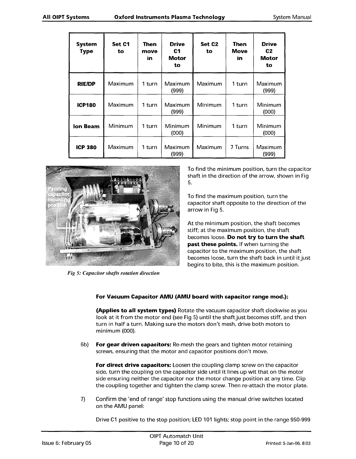
To
find
the
minimum
position,
turn
the
capacitor
shaft
in
the
direction
of
the
arrow,
shown in Fig
5.
To
find
the
maximum
position,
turn
the
capacitor
shaft
opposite
to
the
direction
of
the
arrow
in Fig
5.
At
the
minimum
position,
the
shaft
becomes
stiff;
at
the
maximum
position,
the
shaft
becomes loose.
Do
not
try
to
turn
the
shaft
past
these
points.
If
when
turning
the
capacitor
to
the
maximum
position,
the
shaft
becomes loose,
turn
the
shaft
back in
until
it
just
begins
to
bite, this
is
the
maximum position.
Fig 5: Capacitor shafts rotation direction
For
Vacuum
Capacitor
AMU
(AMU
board
with
capacitor
range
mod.):
(Applies
to
all
system
types)
Rotate
the
vacuum capacitor
shaft
clockwise
as
you
look
at
it
from
the
motor
end
(see
Fig
5)
until
the
shaft
just
becomes stiff, and
then
turn
in
half
a
turn.
Making
sure
the
motors
don't
mesh,
drive
both
motors
to
minimum
(000).
6b) For
gear
driven
capacitors: Re-mesh
the
gears and
tighten
motor
retaining
screws, ensuring
that
the
motor
and capacitor positions
don't
move.
For
direct
drive
capacitors: Loosen
the
coupling
clamp screw on
the
capacitor
side,
turn
the
coupling
on
the
capacitor side
until
it
lines
up
wit
that
on
the
motor
side ensuring
neither
the
capacitor
nor
the
motor
change
position
at
any time. Clip
the
coupling
together
and
tighten
the
clamp screw. Then re-attach
the
motor
plate.
7)
Confirm
the
'end
of
range' stop functions using
the
manual drive switches located
on
the
AMU
panel:
Drive
C1
positive
to
the
stop position;
LED
101
lights; stop
point
in
the
range 950-999
Issue
6:
February
05
DIPT
Automatch
Unit
Page 10
of
20
Printed: 5-lan-06, 8:03
System
Manual
Oxford
Instruments
Plasma
Technology
All OIPT Systems
Drive
C1
negative
to
the
stop position;
LED
102 lights; stop
point
in
the
range
000-
050
Drive
C2
positive
to
the
stop position;
LED
1 lights; stop
point
in
the
range 950-999
Drive
C2
negative
to
the
stop position;
LED
2 lights; stop
point
in
the
range 000 - 050
If
these
aren't
working
as
stated,
refer
to
section 5
or
DIPT
Work
Instruction No. 39
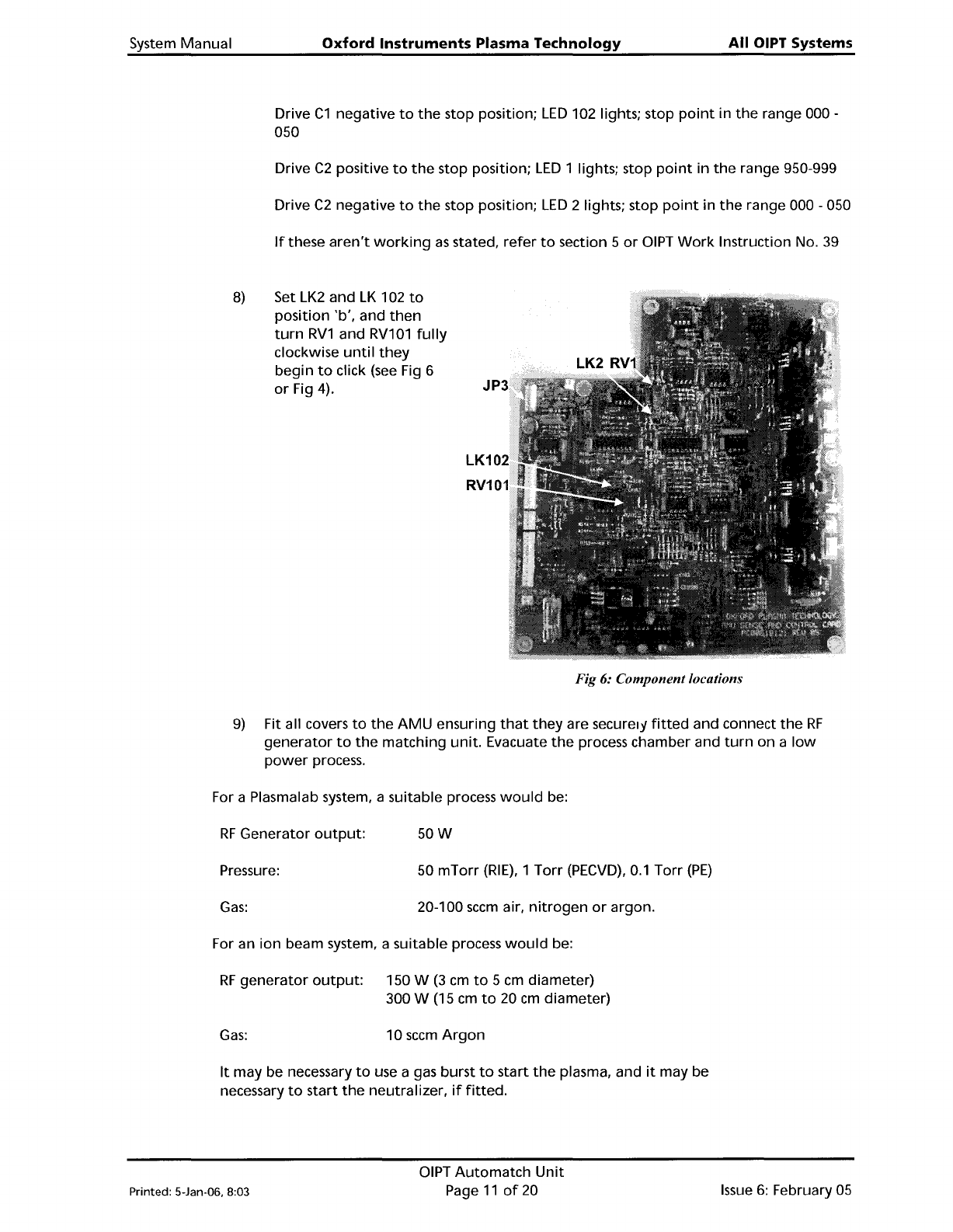
8)
Set
LK2
and
LK
102
to
position
'b',
and
then
turn
RV1
and
RV101
fully
clockwise
until
they
begin
to
click (see Fig 6
or
Fig 4).
Fig 6: Component locations
9)
Fit all covers
to
the
AMU
ensuring
that
they
are securel)'
fitted
and connect
the
RF
generator
to
the
matching
unit.
Evacuate
the
process chamber and
turn
on a
low
power
process.
For a Plasmalab system, a suitable process
would
be:
RF
Generator
output:
Pressure:
Gas:
50W
50
mTorr
(RIE),
1
Torr
(PECVD),
0.1
Torr
(PE)
20-100
sccm
air,
nitrogen
or
argon.
For an
ion
beam system, a suitable process
would
be:
RF
generator
output:
150 W
(3
cm
to
5
cm
diameter)
300 W
(15
cm
to
20
cm
diameter)
Gas:
10
sccm
Argon
It
may be necessary
to
use a gas
burst
to
start
the
plasma, and
it
may be
necessary
to
start
the
neutralizer,
if
fitted.
Printed: 5-Jan-06. 8:03
DIPT
Automatch
Unit
Page
11
of
20
Issue
6:
February 05
All OIPT Systems
Oxford
Instruments
Plasma
Technology
System
Manual
10)
Manually
match
to
the
lowest
possible reflected
power
using
the
AMU
control
panel, and make sure a plasma
is
running.
Adjust
the
error
signal zero
potentiometers
RV1
and
RV2
(located on
the
same side
of
the
AMU
as
the
RF
in
connector;
see
Fig
1),
while
monitoring
the
two
error
signals on
JP3
pins 1 and 3
(See
Fig 6). These should be
less
than
20 mV
when
a match exists.
Amplified
error
signals
are accessible
at
TP
10 and
TP
110; these should be made
as
low
as
possible
when
the
RF
is
well
matched.
For
Vacuum
Capacitor
AMU
(AMU
board
REVOS
and
earlier):
If
it
is
not
possible
to
find
a match
position
due
to
the
match
position
being beyond
the
range
of
the
capacitors, stop
the
process and remove
the
AMU
cover again.
If
C1
is
attempting
to
drive
above
the
maximum position, add 180
pF
padding
capacitor
(Part
Number
94-ECC1218),
or
turn
2 turns anti-clockwise
towards
maximum.
If
C1
is
attempting
to
drive past
the
minimum
position, remove a
padding
capacitor
if
already
fitted,
otherwise
turn
2 turns clockwise
towards
minimum.
If
C2
attempts
to
drive above
the
maximum
position
turn
2 turns anti-clockwise,
if
C2
attempts
to
drive
below
the
minimum
position,
turn
2 turns clockwise.
Whilst
doing
this, be
careful
not
to
turn
the
capacitors beyond
their
physical end stops.
For
Vacuum
Capacitor
AMU
(AMU
board
with
capacitor
range
mod.):
If
C1
attempts
to
drive
above maximum position, add 180
pF
padding
capacitor.
If
C1
is
attempting
to
drive past
the
minimum
position, remove a
padding
capacitor
if
already
fitted.
If
C2
attempts
to
drive past
maximum
or
minimum
position, check
that
the
correct
inductor
is
fitted
and
that
the
capacitors are correctly
fitted
to
the
system.
If
these are correct,
the
match position
is
out
of
the
range
of
C2.
For
Air
Vane
Capacitor
AMU:
If
C1
or
C2
attempts
to
drive above
maximum
position, add 180
pF
padding
capacitor.
If
C1
or
C2
is
attempting
to
drive past
the
minimum
position, remove a
padding
capacitor
if
already
fitted.
It
is
not
necessary
to
reset
the
positions
of
the
Air
Vane Capacitors.
11) Increase
the
RF
power
in
a
few
steps
to
maximum
and check
for
RF
leakage, arcing
or
local overheating.
12) Rematch manually,
when
at
maximum
RF
power,
manually
to
less
than
1%
reflected
power
if
possible;
less
than
3%
is
the
maximum
reflected
power
acceptable. Refine
the
zero settings
of
the
error
signals.
13)
Make
a
note
of
the
capacitor position values
when
a
good
match
is
achieved. Stop
the
process and adjust
the
park
positions
to
a value
below
that
of
the
match position
(within
around
050 units
on
the
position display),
making
sure
that
C2
is
closer
to
its
match
position
than
C1.
Re-start
the
process
with
the
AMU
controller
in
auto
to
make sure
the
match
is
successful.
If
there
is
a large reflected
power,
repeat
Step 10.
If
there
is
a small
amount
of
reflected power,
which
can't
be reduced manually,
RV1
and
RV2
on
the
side
of
the
AMU
can be used
to
make
finer
adjustments
when
in
auto
mode.
14)
If
the
capacitors oscillate
when
in
auto,
reduce
the
gain
of
the
control
circuit by
slowly
turning
RV1
and
RV101
anti-clockwise
(if
C2
oscillates adjust
RV1,
if
C1
oscillates adjust RV101)
until
oscillations stop.
If
the
potentiometer's
RV1
or
RV101
begin
to
click
before
the
oscillations have ceased,
turn
them
fUlly clockwise
until
they
begin
to
click again and change
LK2
(corresponding
to
RV1)
or
LK102
Issue
6:
February 05
DIPT
Automatch
Unit
Page
12
of
20 Printed: 5-Jan-06, 8:03