Oxford-100-Manual.pdf - 第43页
System Manual Oxford Instruments Plasma Technology Plasma lab System 100 3.4 94·100·3·41C ICP 180 chamber kit with gate valve The ICP chamber kit comprises the following components: Process chamber. Pumping port isolatio…
Plasma
lab
System
100
Oxford
Instruments
Plasma
Technology
System Manual
Emergency
Off
I Electrical
24V
Process
line
24V
Chamber
lid
line
Fail
Interlock
Fail
Restore
Fail
Restore
Fail Restore
System/Controller
OFF
Restart
Required
ON
ON
RF
Generator
OFF
Powered, NOT
OFF
Powered,
OFF
Powered, NOT
active
NOT active
active
Process
Gases
OFF
Powered, NOT
OFF
Powered,
OFF
Powered, NOT
active NOT active
active
Automatic
**
Pressure
CLOSED CLOSED
NO
NO
CLOSED CLOSED
Controller
Valve CHANGE
CHANGE
Load lock
*
Slit Valve HOLD
HOLD
HOLD HOLD
HOLD HOLD
Pumps
OFF
Pumps
must
be
NO
NO
OFF
Pumps must
restarted CHANGE
CHANGE
be restarted
*
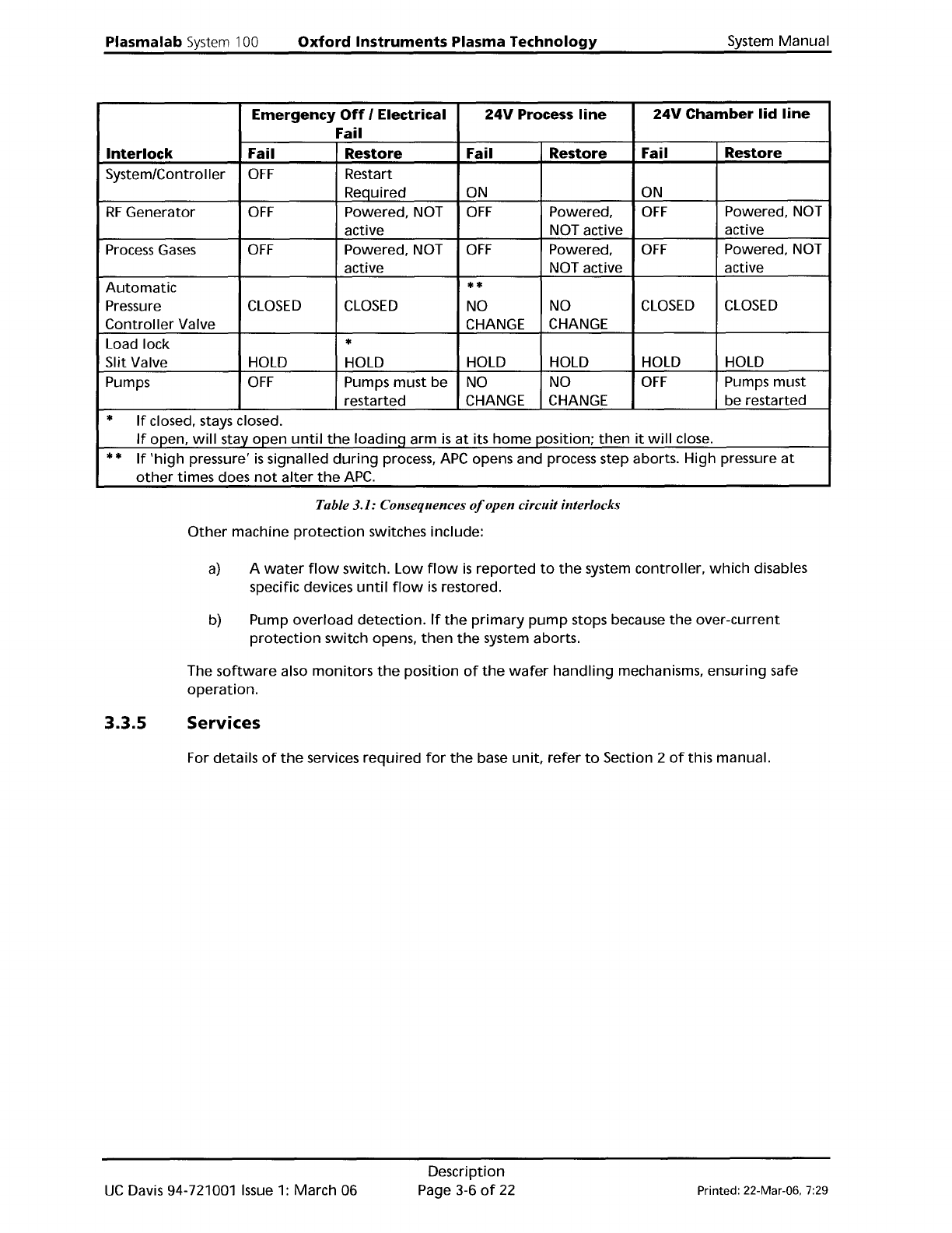
If
closed, stays closed.
If
open,
will
stay open
until
the
loadinq
arm
is
at
its
home
position;
then
it
will
close.
**
If
'high
pressure'
is
signalled
during
process,
APC
opens and process step aborts. High pressure
at
other
times does
not
alter
the
APC.
Table 3.1: Consequences
%pen
circuit interlocks
Other
machine
protection
switches include:
a)
A
water
flow
switch.
Low
flow
is
reported
to
the
system controller,
which
disables
specific devices
until
flow
is
restored.
b) Pump
overload
detection.
If
the
primary
pump
stops because
the
over-current
protection
switch opens,
then
the
system aborts.
The
software
also
monitors
the
position
of
the
wafer
handling
mechanisms, ensuring safe
operation.
3.3.5
Services
For details
of
the
services
required
for
the
base
unit,
refer
to
Section 2
of
this manual.
UC
Davis 94-721001
Issue
1:
March 06
Description
Page 3-6
of
22
Printed: 22-Mar-06, 7:29
System
Manual
Oxford
Instruments
Plasma
Technology
Plasma
lab
System
100
3.4
94·100·3·41C
ICP
180
chamber
kit
with
gate
valve
The
ICP
chamber
kit
comprises
the
following
components:
Process
chamber.
Pumping
port
isolation valve and
automatic
pressure
controller
suitable
for
use
with
a
turbomolecular
pump.
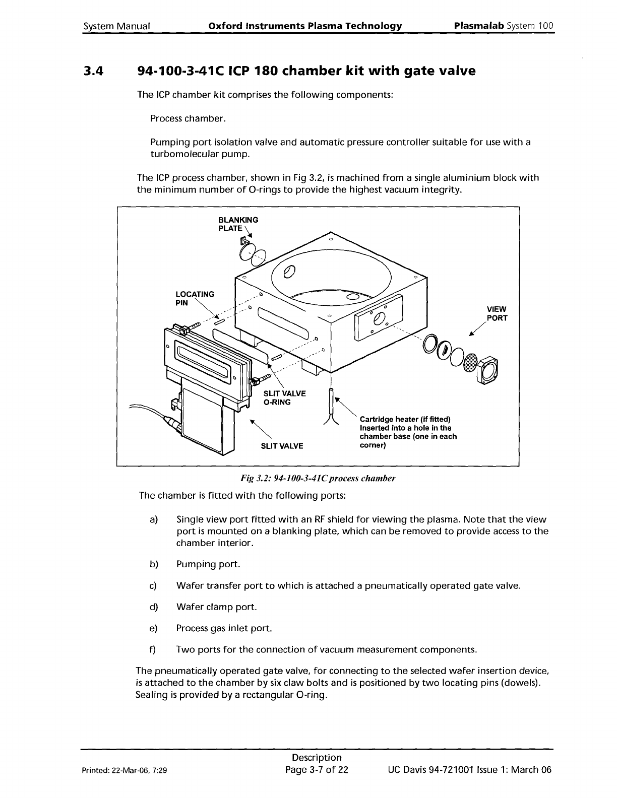
The
ICP
process chamber, shown
in
Fig 3.2,
is
machined
from
a single
aluminium
block
with
the
minimum
number
of
O-rings
to
provide
the
highest vacuum
integrity.
LOCATING
SLIT
VALVE
!
1
~
C''''''g
......
,
(0
fltted)
Inserted
into
a hole in the
chamber base (one in each
corner)
VIEW
Fig 3.2: 94-100-3-41Cprocess
chamber
The chamber
is
fitted
with
the
following
ports:
a)
Single
view
port
fitted
with
an
RF
shield
for
viewing
the
plasma.
Note
that
the
view
port
is
mounted
on
a
blanking
plate,
which
can
be
removed
to
provide
access
to
the
chamber
interior.
b) Pumping
port.
c)
Wafer
transfer
port
to
which
is
attached a
pneumatically
operated
gate
valve.
d)
Wafer
clamp
port.
e)
Process gas
inlet
port.
f)
Two
ports
for
the
connection
of
vacuum measurement components.
The
pneumatically
operated
gate
valve,
for
connecting
to
the
selected
wafer
insertion device,
is
attached
to
the
chamber
by
six claw
bolts
and
is
positioned by
two
locating
pins (dowels).
Sealing
is
provided
by
a rectangular O-ring.
Printed: 22-Mar-06, 7:29
Description
Page 3-7
of
22
UC
Davis 94-721001
Issue
1: March 06
Plasmalab
System
100
Oxford
Instruments
Plasma
Technology
System
Manual
3.4.1
3.4.2
94-100-3-00/21P
Process
chamber
electrical
heating
kit
The electrical
heating
kit
comprises
four
cartridge
heaters; inserted
into
holes
at
the
corners
in
the
base
of
the
process chamber,
see
Fig 3.2. Heater
control
is
via a
unit
mounted
on
the
console,
where
the
temperature
can
be
set manually. A
temperature
in
the
range 50°C
to
60°C
is
recommended
for
most
processes.
WARNING
IF THE PROCESS CHAMBER TEMPERATURE IS
SET
TO A VALUE ABOVE
GOGC,
CONTACT
WITH IT
CAN
CAUSE BURNS.
BEFORE OPERATING THE CHAMBER ABOVE
GOGC,
ENSURE THAT EXTERNAL HEAT
SHIELDS ARE FITTED.
94-100-3-00/05
200mm
Pumpdown
pipe
heater
kit
This
heating
kit
is
applied
to
the
pump-down
pipe
to
give
optimum
vacuum performance and
to
minimise
the
deposition
of
loosely
adherent
material,
which
might
generate
particulates.
UC
Davis 94-721001
Issue
1:
March
06
Description
Page 3-8
of
22
Printed: 22-Mar-06, 7:29