Oxford-100-Manual.pdf - 第48页
Plasma lab System 100 Oxford Instruments Plasma Technology System Manual 3.6 94-100-6-500/200 500W RF generator / OIPT AMU kit This kit comprises a 500W RF Generator and an OIPT Automatch Unit. The RF generator produces …
System
Manual
Oxford
Instruments
Plasma
Technology
Plasma
lab
System
100
COMPR SSED
AIR
CYliNDER
(ONE
EAcH
SIDE
OFCL~PING
PLATE)
~
:::::::::=';;;;;;;;;;;;;;;;;;;;;:;::=="3-pin
wafer
I
~---Hrt-:.".....~_
- - _S!!0lQ!t -
~
TABLE WAFER
CLAMP
DARK SPACE
6~zr'"""
WAFER
LIFT
ASSEMBLY
(FITS INSIDE
TABLE SUPPORT
TUBE)
TABLE SUPPORT
TUBE
o RING
PUMPDOWN
PIPE FLANGE
SAFETY RELIEF
VALVE
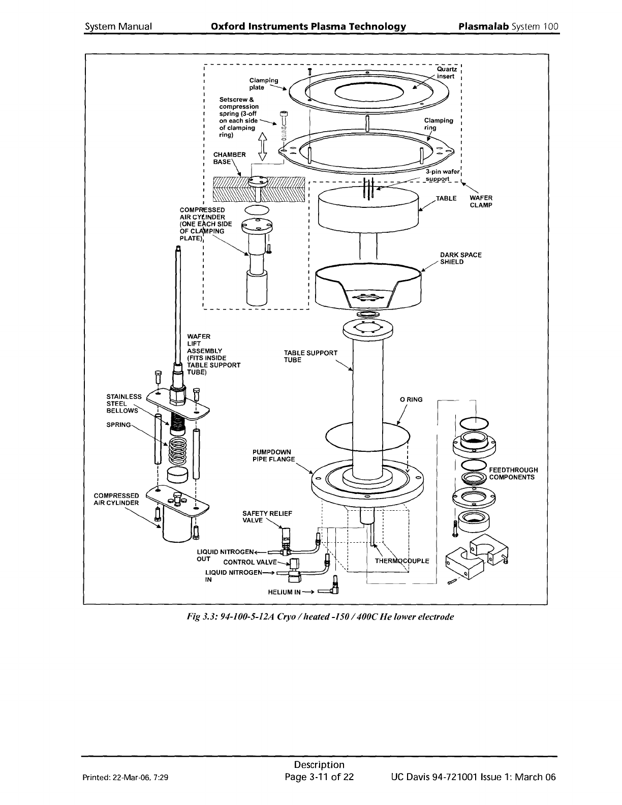
Fig 3.3: 94-100-5-12A Cryo / heated-150/ 400C
He
lower electrode
Printed: 22-Mar-06. 7:29
Description
Page3-11of22
UC
Davis 94-721001
Issue
1: March 06
Plasma
lab
System
100
Oxford
Instruments
Plasma Technology System Manual
3.6
94-100-6-500/200
500W
RF
generator
/ OIPT
AMU
kit
This
kit
comprises a 500W
RF
Generator
and an
OIPT
Automatch
Unit.
The
RF
generator
produces a 13.56MHz
output.
which
is
fed
via
the
automatch
unit
to
the
lower
electrode
to
produce
the
plasma. The
automatch
unit
adjusts
the
impedance
of
its
output
to
match
the
impedance
of
the
lower
electrode
to
ensure
maximum
power
transfer.
For details
of
these units,
refer
to
the
manufacturer's
literature
in
Volume
3
of
this manual.
The
automatch
unit
can be
manually
adjusted
if
necessary,
see
Operator
Adjustments in
Section 5
of
this manual.
3.7
94-100-6-56
ICP
180
Inductively
Coupled
Plasma Source
The
inductively
coupled plasma source
is
180mm in diameter,
which
gives
uniformity
suitable
for
use
with
wafers
up
to
four
inches in diameter.
An
RF
generator
(3kW 13.56MHz) and
automatch
unit
are included. A
quartz
or
alumina discharge chamber
is
supplied, according
to
the
process specification. For
full
details
of
this source,
refer
to
the
ICP
180 manual (provided
as
a
supplement
to
this manual -
refer
to
the
contents list).
3.8
Vacuum
system
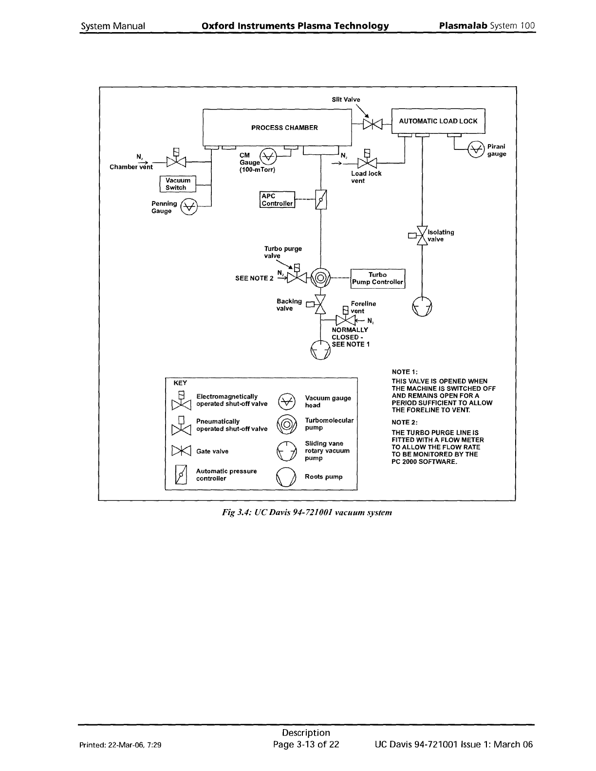
The vacuum system
is
shown
in Fig 3.4.
The process chamber
is
pumped
by an Alcatel ATP900
turbomolecular
pump
via an
Automatic
Pressure
Controller
(APC). The
turbomolecular
pump
is
backed via an isolation valve by an
Alcatel 2063
C2
rotary
vane
pump.
The process chamber process pressure
is
measured
by
a
temperature
compensated 100-mTorr
Capacitance
Manometer
gauge.
Note
that
the
CM
gauge
output
does
not
stabilise
until
it
has
been switched
on
and
under
vacuum
for
15 minutes.
Base
pressure
is
measured
by
an active Penning gauge,
which
is
disabled
at
pressures above
10 mTorr.
A Vacuum Switch
monitors
the
chamber pressure.
When
the
pressure falls
below
600 mbar, its
contacts close
to
enable
the
24V process line and
allow
the
process gases and
the
RF
to
operate.
The
automatic
load lock
is
pumped
by
an Alcatel 2015
C2
rotary
vane pump. A Pirani
gauge
measures pressure.
For details
of
the
vacuum pumps and gauges,
refer
to
the
manufacturer's
literature
in
Volume
3
of
this manual.
UC
Davis 94-721001
Issue
1:
March 06
Description
Page 3-12
of
22
Printed: 22-Mar-06, 7:29
System
Manual
Oxford
Instruments
Plasma
Technology
Plasma
lab
System
100
N,
Chamber
wi'nt,--I/
-
......
PROCESS CHAMBER
Turbo
purge
valve
...............
SEE NOTE 2
N,
Backing
valve
Load
lock
vent
Turbo
Pump
Controller
Pirani
gauge
Isolating
valve
NOTE 1:
KEY
THIS VALVE
IS
OPENED WHEN
J:J
THE MACHINE IS SWITCHED OFF
Electromagnetically
e
Vacuum gauge
AND REMAINS OPEN FOR A
operated
shut-off
valve
head
PERIOD SUFFICIENT
TO
ALLOW
THE FORELINE TO
VENT.
~
Pneumatically
@
Turbomolecular
NOTE
2:
operated
shut-off
valve
pump
THE TURBO PURGE LINE IS
0
Sliding
vane
FITTED WITH A FLOW METER
[)k]
TO
ALLOW
THE FLOW RATE
Gate valve
rotary vacuum
TO
BE MONITORED
BY
THE
pump
PC
2000 SOFTWARE.
[2]
Automatic
pressure
0
Roots
pump
controller
Fig 3.4: UC Davis 94-721001 vacuum system
Printed: 22-Mar-06, 7:29
Description
Page 3-13
of
22
UC
Davis 94-721001
Issue
1:
March 06