Oxford-100-Manual.pdf - 第54页
Plasma lab System 100 Oxford Instruments Plasma Technology System Manual 3.10 94-100-10-0SC Single wafer automatic load lock Fig 3.8: Single wafer automatic load lock UC Davis 94-721001 Issue 1: March 06 Description Page…
System
Manual
Oxford
Instruments
Plasma
Technology
Plasma
lab
System
100
3.9.3
94-81-9-21
Standard
toxic
gas
line
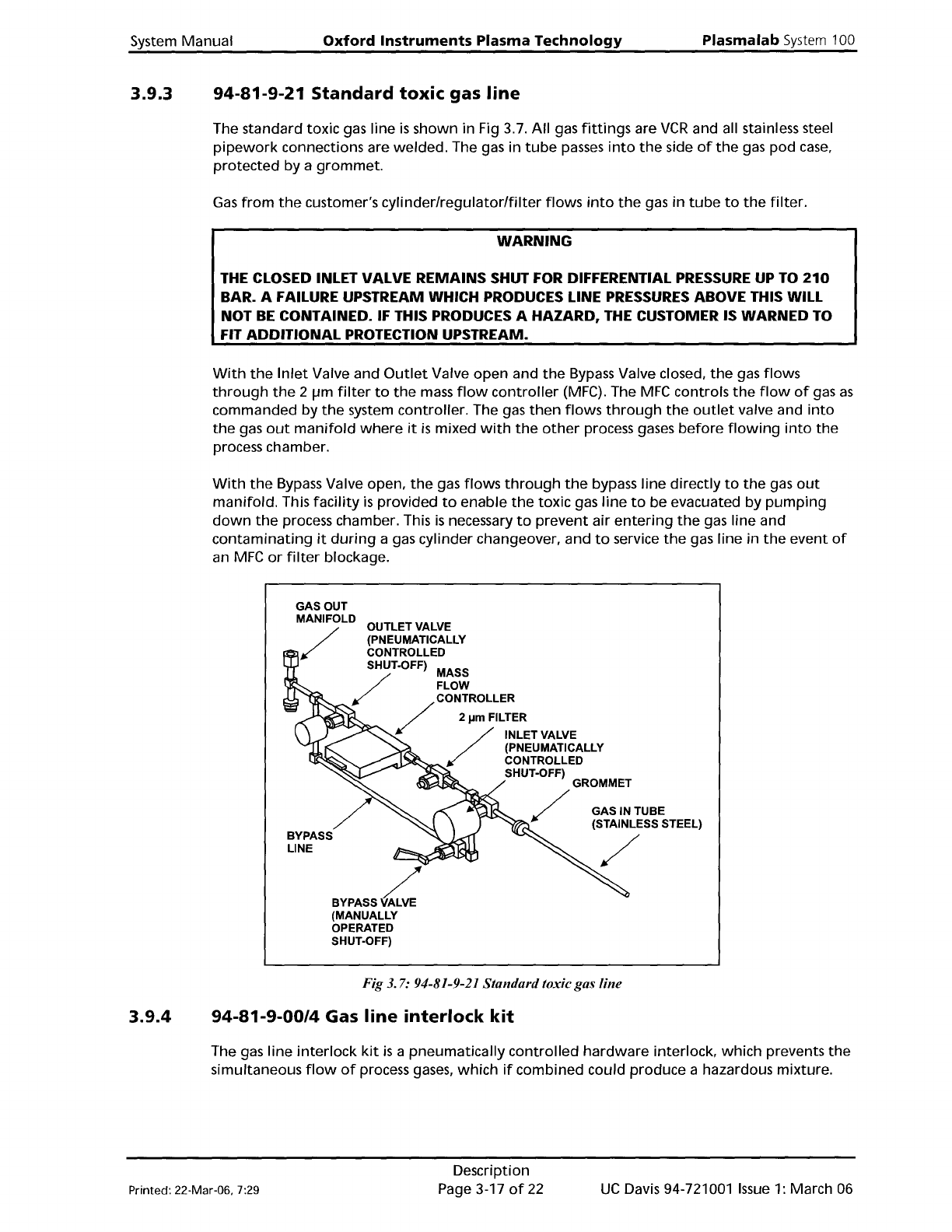
The standard
toxic
gas line
is
shown in Fig 3.7.
All
gas
fittings
are
VCR
and all stainless steel
pipework
connections are
welded.
The gas in
tube
passes
into
the
side
of
the
gas
pod
case,
protected
by a
grommet.
Gas
from
the
customer's
cylinderlregulator/filter
flows
into
the
gas
in
tube
to
the
filter.
WARNING
THE CLOSED INLET VALVE
REMAINS
SHUT FOR DIFFERENTIAL
PRESSURE
UP TO
210
BAR. A FAILURE UPSTREAM WHICH PRODUCES LINE
PRESSURES
ABOVE THIS WILL
NOT
BE
CONTAINED.
IF
THIS PRODUCES A HAZARD, THE CUSTOMER IS WARNED TO
FIT
ADDITIONAL
PROTECTION UPSTREAM.
With
the
Inlet
Valve and
Outlet
Valve
open
and
the
Bypass
Valve closed,
the
gas
flows
through
the
2
Ilm
filter
to
the
mass
flow
controller
(MFG).
The
MFC
controls
the
flow
of
gas
as
commanded
by
the
system
controller.
The gas
then
flows
through
the
outlet
valve and
into
the
gas
out
manifold
where
it
is
mixed
with
the
other
process gases
before
flowing
into
the
process chamber.
With
the
Bypass Valve open,
the
gas
flows
through
the
bypass
line
directly
to
the
gas
out
manifold.
This
facility
is
provided
to
enable
the
toxic gas
line
to
be evacuated by
pumping
down
the
process chamber. This
is
necessary
to
prevent
air
entering
the
gas line and
contaminating
it
during
a gas cylinder changeover, and
to
service
the
gas line in
the
event
of
an
MFC
or
filter
blockage.
BYPASS
v::::
(MANUALLY
OPERATED
SHUT-OFF)
GAS IN TUBE
(STAINLESS STEEL)
/
BYPASS
LINE
OUTLET VALVE
(PNEUMATICALLY
CONTROLLED
SHUT-OFF) MASS
/
FLOW
/
CONTROLLER
2
j.lm
FILTER
/
INLET VALVE
(PNEUMATICALLY
~~~
CONTROLLED
SHUT-OFF)
GROMMET
/
3.9.4
Fig
3.
7:
94-81-9-21 Standardtoxicgas line
94-81-9-00/4
Gas
line
interlock
kit
The gas line
interlock
kit
is
a
pneumatically
controlled
hardware
interlock,
which
prevents
the
simultaneous
flow
of
process gases,
which
if
combined could produce a hazardous mixture.
Printed: 22-Mar-06, 7:29
Description
Page 3-17
of
22
UC
Davis 94-721001
Issue
1: March 06
Plasma
lab
System
100
Oxford
Instruments
Plasma
Technology
System
Manual
3.10
94-100-10-0SC
Single
wafer
automatic
load
lock
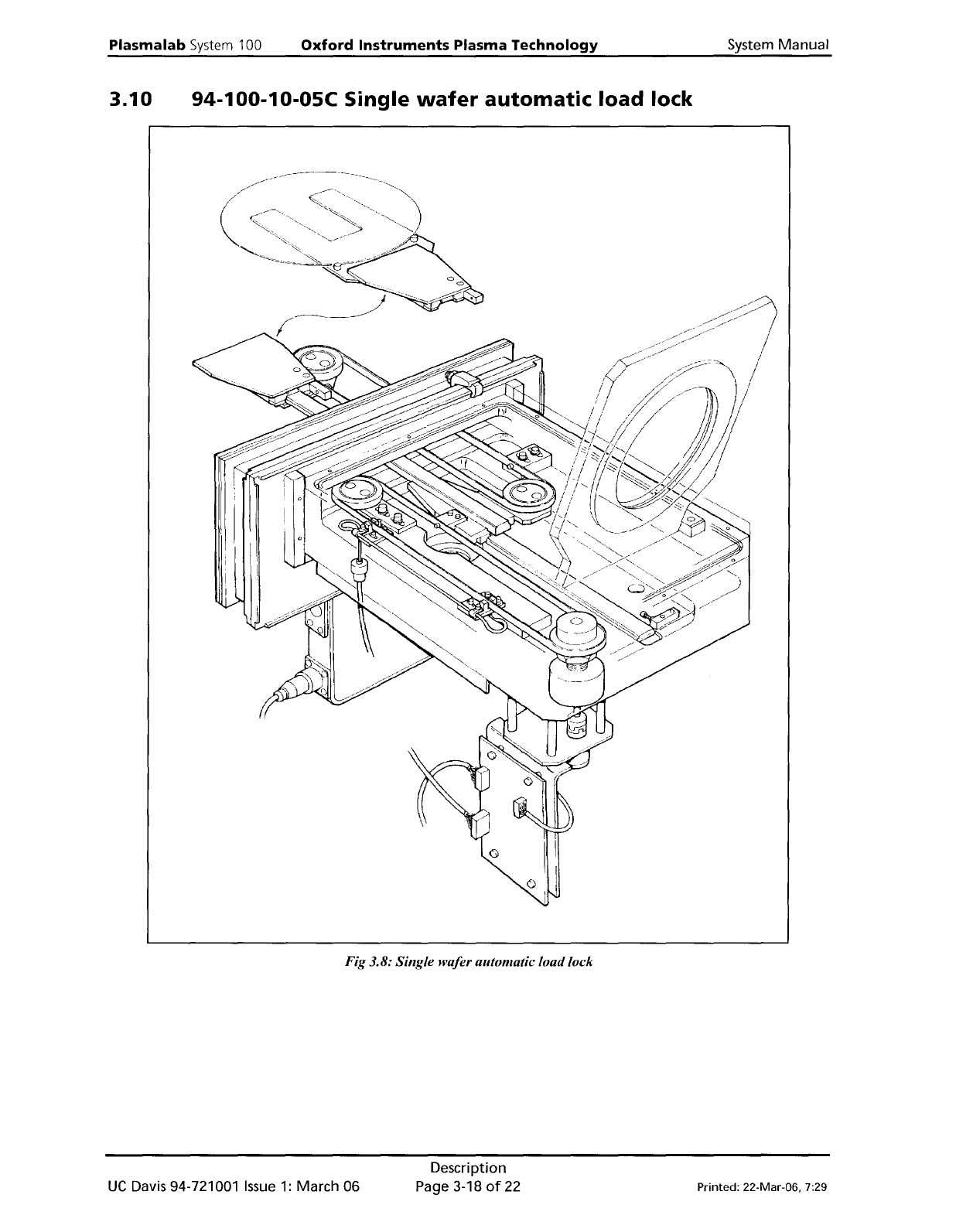
Fig 3.8: Single wafer automatic load lock
UC
Davis 94-721001
Issue
1:
March 06
Description
Page 3-18
of
22
Printed: 22-Mar-06, 7:29
System
Manual
Oxford
Instruments
Plasma
Technology
Plasmalab System 100
3.10.1
The
automatic
load lock, shown in Fig 3.8, enables
wafer
loading
and
unloading
to
be
automatically
achieved
under
vacuum. These operations are
controlled
by
computer,
requiring
minimum
operator
involvement. The
Oxford
Instruments Plasma Technology design
results in a very compact load lock (395
mm
long
with
400
mm
of
wafer
support
travel). The
load lock
is
capable
of
handling
MESC'
standard
wafers
up
to
200
mm
diameter.
Wafer
transfer
mechanism
operating
principle
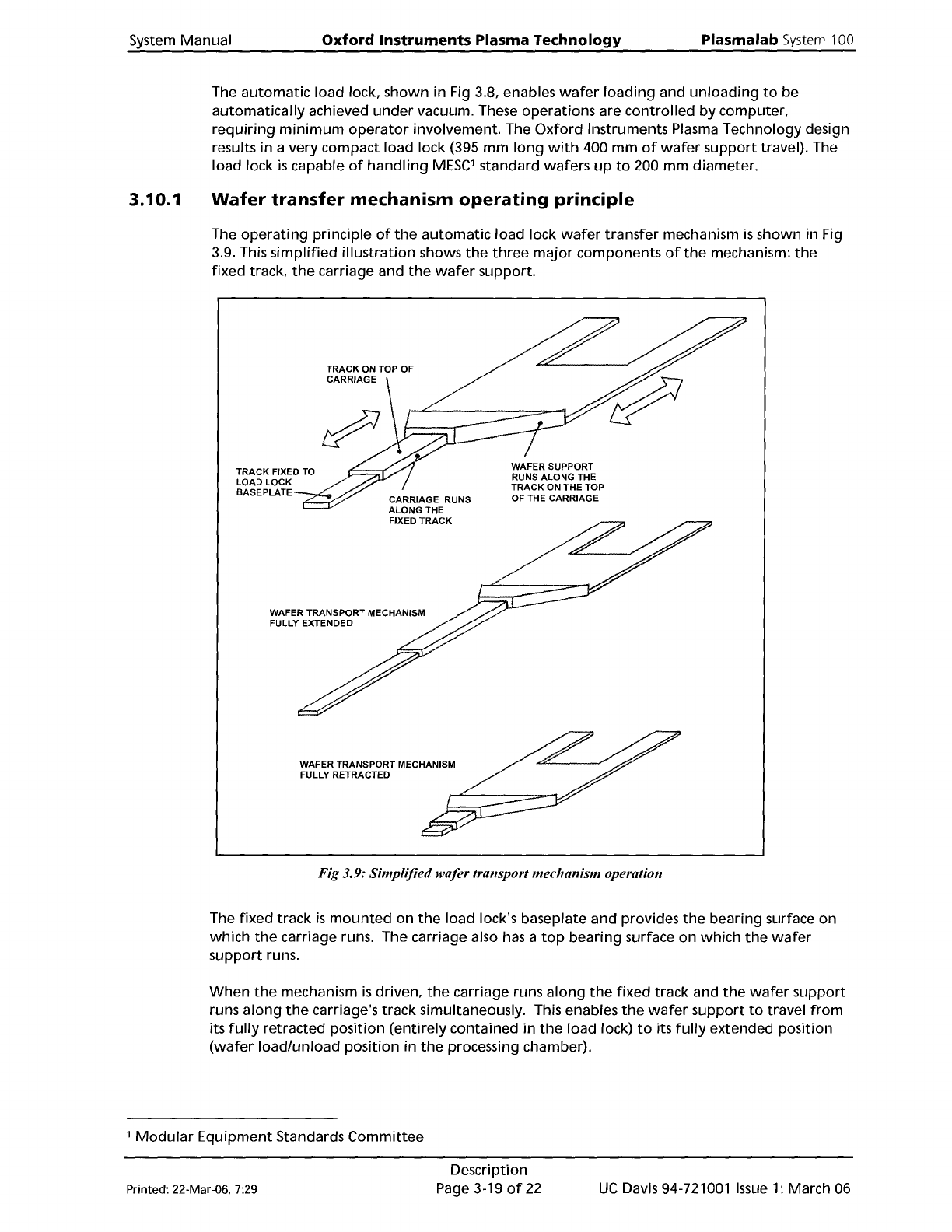
The
operating
principle
of
the
automatic
load
lock
wafer
transfer
mechanism
is
shown in Fig
3.9. This
simplified
illustration
shows
the
three
major
components
of
the
mechanism:
the
fixed track,
the
carriage and
the
wafer
support.
TRACK FIXED TO
LOAD LOCK
BASEPLATE
WAFER TRANSPORT MECHANISM
FULLY EXTENDED
WAFER TRANSPORT MECHANISM
FULLY RETRACTED
WAFER SUPPORT
RUNS ALONG THE
TRACK
ON
THE TOP
OF THE CARRIAGE
Fig 3.9: Simplified wafer transport mechanism operation
The
fixed
track
is
mounted
on
the
load lock's baseplate
and
provides
the
bearing surface on
which
the
carriage runs. The carriage also has a
top
bearing
surface on
which
the
wafer
support
runs.
When
the
mechanism
is
driven,
the
carriage runs
along
the
fixed
track and
the
wafer
support
runs
along
the
carriage's track simultaneously. This enables
the
wafer
support
to
travel
from
its
fully
retracted
position
(entirely
contained
in
the
load lock)
to
its
fully
extended position
(wafer
load/unload
position
in
the
processing chamber).
,
Modular
Equipment
Standards
Committee
Printed: 22-Mar-06, 7:29
Description
Page 3-19
of
22
UC
Davis 94-721001
Issue
1: March 06