Oxford-100-Manual.pdf - 第58页
Plasma lab System 100 Oxford Instruments Plasma Technology System Manual 3.10.3 As Steel Belt 2 travels with respect to the Carriage, it causes the Wafer Support attached to it to travel along the Carriage. 6) As the Waf…
System
Manual
Oxford
Instruments
Plasma
Technology
Plasma
lab
System
100
WAFER
SUPPORT
PULLEY
WHEEL 4
(ATTACHED TO
WAFER SUPPORT)
CARRIAGE
(ATTACHED TO
STEEL BELT
1)
PULLEY
BELT RETAINING
WHEEL 2
POST
PHOTO
DIODE
1
STEEL
BELT
1
PULLEY
WHEEL 3
(ATTACHED TO
PHOTO
CARRIAGE)
DIODE
2
PULLEY
TRACK
WHEEL 1
(DRIVEN)
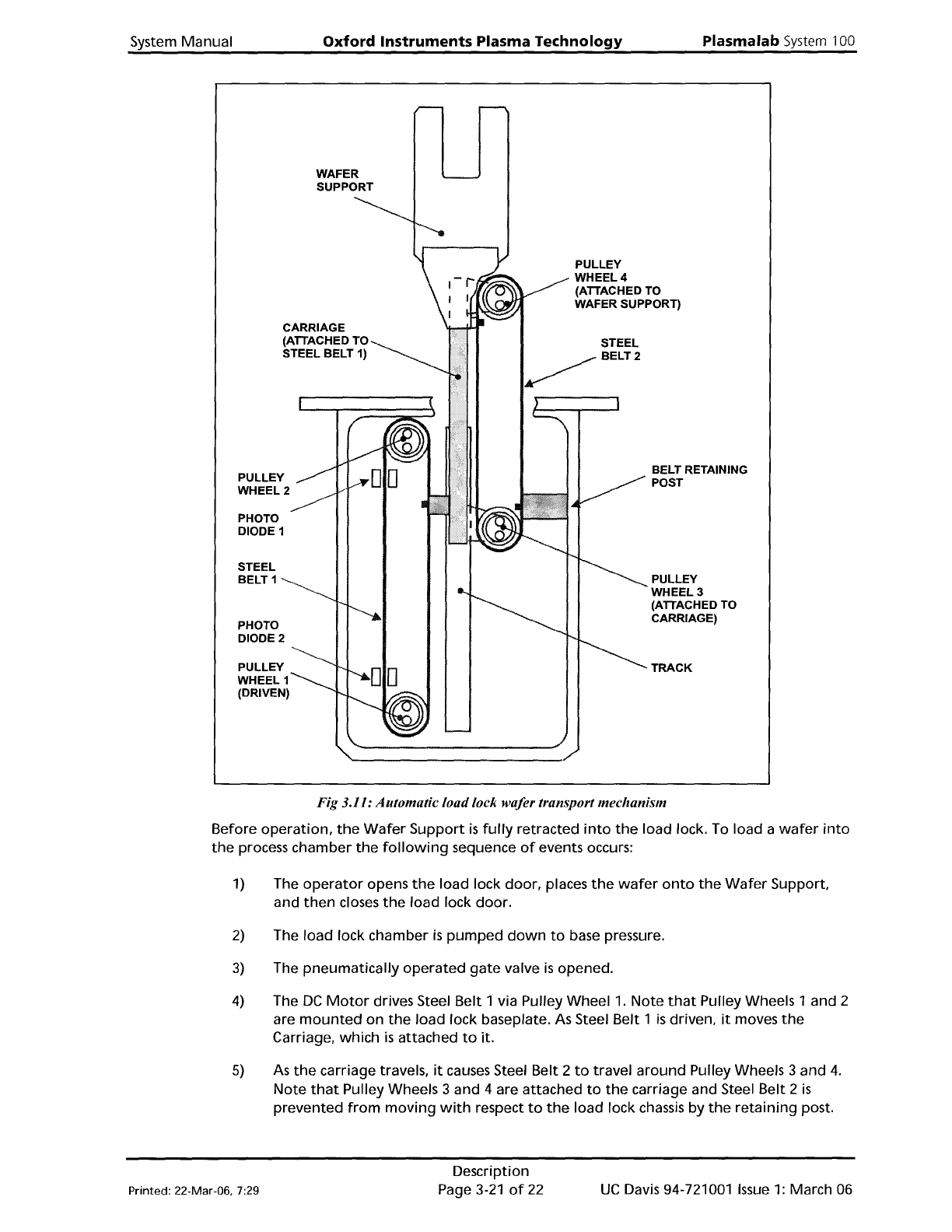
Fig 3.11: Automatic loadlock wafer transport mechanism
Before
operation,
the
Wafer
Support
is
fUlly retracted
into
the
load lock. To load a
wafer
into
the
process chamber
the
following
sequence
of
events occurs:
1)
The
operator
opens
the
load lock
door,
places
the
wafer
onto
the
Wafer
Support
and
then
closes
the
load
lock
door.
2)
The
load
lock chamber
is
pumped
down
to
base pressure.
3)
The
pneumatically
operated
gate
valve
is
opened.
4)
The
DC
Motor
drives Steel
Belt
1 via Pulley Wheel
1.
Note
that
Pulley Wheels 1 and 2
are
mounted
on
the
load
lock baseplate. As Steel Belt 1
is
driven,
it
moves
the
Carriage, which
is
attached
to
it.
5)
As
the
carriage travels,
it
causes Steel Belt 2
to
travel
around
PUlley Wheels 3 and
4.
Note
that
PUlley Wheels 3 and 4 are attached
to
the
carriage and Steel Belt 2
is
prevented
from
moving
with
respect
to
the
load lock chassis by
the
retaining
post.
Printed: 22-Mar-06, 7:29
Description
Page
3-21
of
22
UC
Davis 94-721001
Issue
1:
March 06
Plasma
lab
System
100
Oxford
Instruments
Plasma Technology
System
Manual
3.10.3
As
Steel Belt 2 travels
with
respect
to
the
Carriage,
it
causes
the
Wafer
Support
attached
to
it
to
travel
along
the
Carriage.
6)
As
the
Wafer
Support
reaches
the
end
of
its travel, a
hole
in Steel Belt 1
is
detected
by
Photo
Diode 2
to
stop
the
DC
Motor.
7)
The
wafer
is
lifted
from
the
wafer
support
by a
wafer
lift
within
the
processing
chamber,
the
wafer
support
is
withdrawn
from
the
chamber, and
the
wafer
is
lowered
onto
the
processing
table
by
the
wafer
lift.
8)
As
the
Wafer
Support
reaches its
fully
retracted position
within
the
load lock,
the
hole
in Steel Belt 1
is
detected by Photo Diode 1
to
stop
the
DC
motor.
9)
The
gate
valve
is
closed and
the
load lock can be vented
if
required.
The above sequence
of
events
is
repeated
to
remove
the
wafer
from
the
processing chamber.
Wafer
support
(end
effector)
The
automatic
load
lock end
effector
(wafer
support) can accommodate
wafer
diameters
of
3"
to
8".
See
Section 6 (Maintenance)
for
the
end
effector
wafer
size
adjustment
procedure.
UC
Davis 94-721001
Issue
1:
March 06
Description
Page 3-22
of
22
Printed: 22-Mar-06, 7:29
System
Manual
Oxford
Instruments
Plasma
Technology
Plasma
lab
System
100
4.
Installation
and
commissioning
4.
Installation
and
commissioning
4-1
4.1
Introduction
.4-2
4.2
Installing
the
system
4-2
4.2.1 Unpacking 4-2
4.2.2 Positioning
the
system components 4-3
4.2.3 Connecting
the
services 4-4
4.3
Commissioning
the
system 4-6
4.4
System adjustments .4-6
4.4.1 Heater/Chillers .4-6
4.4.2 Process
pump
purge
.4-6
Fig 4.1: 3-phase supply cable connections
at
the
power
box
4-5
Printed: 16 March 200611:59
Installation and Commissioning
Page
4-1
of
8
Issue
4:
March
as