Oxford-100-Manual.pdf - 第99页
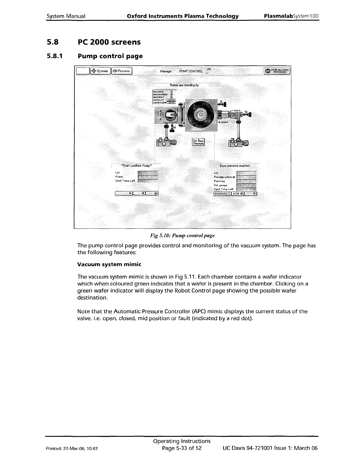
System Manual Oxford Instruments Plasma Technology PlasmalabSystem 100 5.8 5.8.1 PC 2000 screens Pump control page Fig 5.10: Pump control page The pump control page provides control and monitoring of the vacuum system. T…
PlasmalabSystem100
Oxford
Instruments
Plasma Technology
System Manual
5.7.3
Rotary/dry
pump
N
z
purge
flow
rate
adjustment
CAUTION
If
the
rotary/dry
pump's
N
z
purge
flow
rate
is
inadequate,
damage
to
the
pump
could occur.
Ensure
that
the
flow
rate
is
set
to
the
value
recommended
by
the
pump
manufacturer.
The
rotary/dry
pump's
N
z
purge
flow
rate
is
set
at
the
factory
before
system
shipment
and
should
not
need adjustment. However,
the
pump
purge
rate
will
need
to
be
confirmed
on
installation
and
at
any
time
the
purge
gas supply pressure changes significantly.
If
adjustment
is
necessary,
refer
to
Appendix
R in this manual.
UC
Davis 94-721001
Issue
1:
March 06
Operating
Instructions
Page 5-32
of
52
Printed: 22-Mar-06. 10:42
System
Manual
Oxford
Instruments
Plasma
Technology
PlasmalabSystem100
5.8
5.8.1
PC
2000
screens
Pump
control
page
Fig 5.10: Pump controlpage
The
pump
control
page provides
control
and
monitoring
of
the
vacuum system. The page
has
the
following
features:
Vacuum
system
mimic
The vacuum system
mimic
is
shown in Fig 5.11.
Each
chamber contains a
wafer
indicator
which
when
coloured green indicates
that
a
wafer
is
present in
the
chamber. Clicking on a
green
wafer
indicator
will
display
the
Robot
Control
page
showing
the
possible
wafer
destination.
Note
that
the
Automatic
Pressure
Controller
(APC)
mimic displays
the
current
status
of
the
valve, i.e. open, closed,
mid
position
or
fault
(indicated
by
a red dot).
Printed: 22-Mar-06, 10:42
Operating
Instructions
Page 5-33
of
52
UC
Davis 94-721001
Issue
1:
March 06
PlasmalabSystem100
Oxford
Instruments
Plasma
Technology
AUTOMADCPRESSURE
CONTROLLER
System Manual
TURBO
PURGE
VALVE
ROTARYVANE/DRY PUMP ROTARYVANE/DRY PUMP
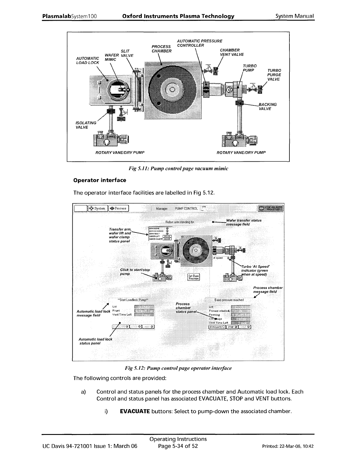
Fig 5.11: Pump controlpage vacuum mimic
Operator
interface
The
operator
interface
facilities are labelled in Fig 5.12.
Fig 5.12: Pump controlpage operator interface
The
following
controls are provided:
a)
Control and status panels
for
the
process chamber and
Automatic
load lock.
Each
Control
and status panel has associated EVACUATE,
STOP
and VENT buttons.
i)
EVACUATE buttons: Select
to
pump-down
the
associated chamber.
UC
Davis 94-721001
Issue
1:
March 06
Operating
Instructions
Page 5-34
of
52
Printed: 22-Mar-06, 10:42