Operating Manual - 第13页
4022 591 960 62 Operating Manual 02.0 2 FCM Mu ltif lex 11 General Mach ine Informatio n 2.7 Gen eral Pr oc edures 2.7.1 Lowering Placement Modules Unlock a pl acemen t module by pushin g it up a nd let it go do wn by it…
4022 591 96062 Operating Manual
02.02 FCM Multiflex 10
General Machine Information
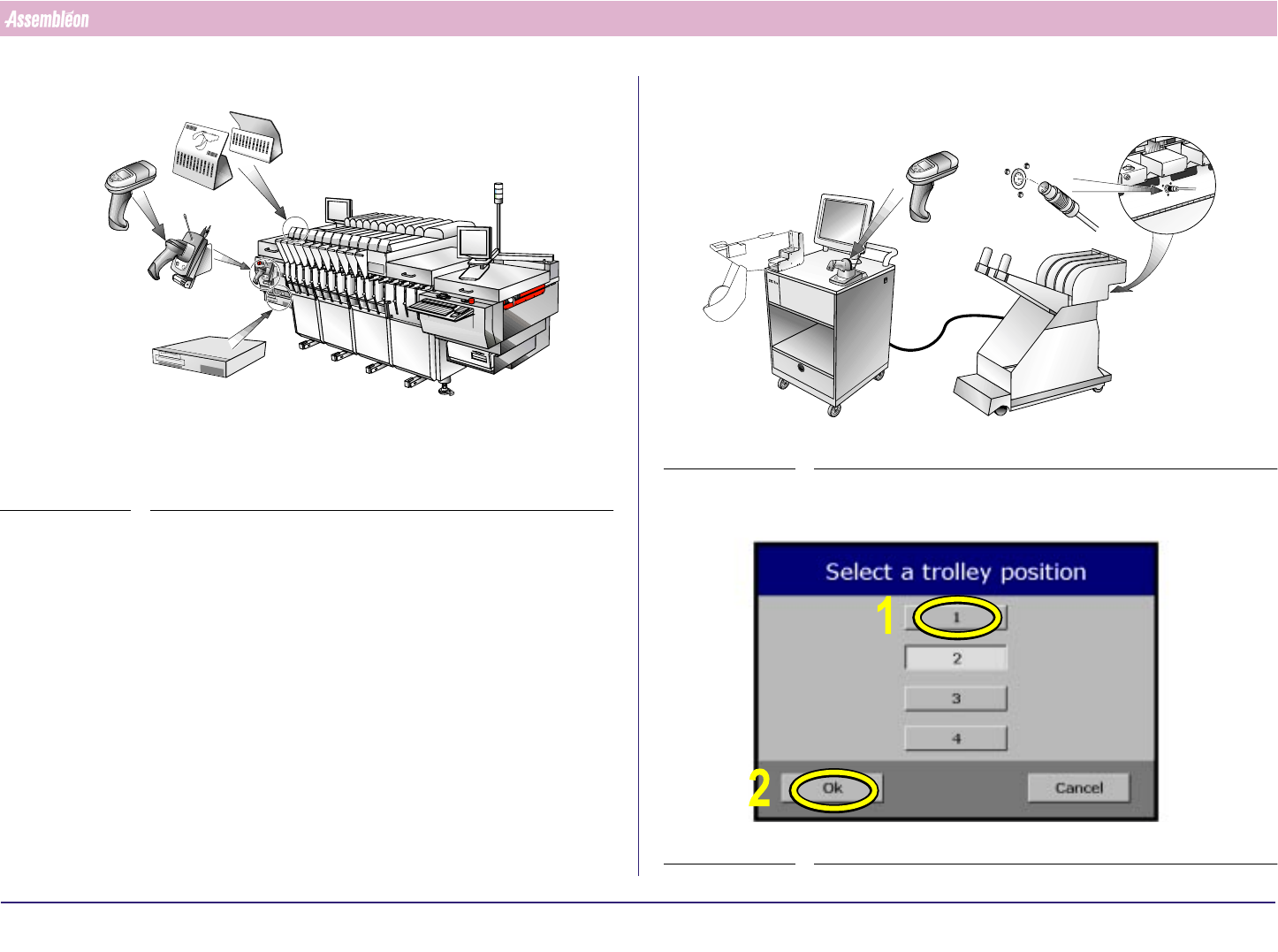
2.6 SVS Pro Items
FIGURE 8
For all SVS Pro operations instructions are displayed on the screen of the
scanner.
Functionality of the buttons on the scanner:
■ [Enter] button: select the current item (e.g. the error that is currently
on the display) or acknowledge a question (e.g. "
Overwrite ?").
■ [▲ ] button: scroll to previous item.
■ [▼] button: scroll to next item or skip this item.
SVS Pro messages can be displayed on the monitor of the machine (select
Video - SVS), but can only be handled with the buttons on the scanner.
R
E
S
C
A
N
P
A
R
T
N
U
M
B
E
R
S
PAR
D
AT
A
C
H
A
N
G
IN
G
BA
TT. FULL
-
1
-
1
0
1
1
0
2
1
0
3
1
0
4
1
0
5
106
107
1
0
8
1
0
9
1
1
0
1
1
1
L
A
N
E
1
L
A
N
E
2
-1
-
1
0
1
1
0
2
1
0
3
104
1
0
5
1
0
6
107
1
0
8
1
0
9
1
1
0
1
1
1
Position indicatorsScanner (with
screen and
buttons)
Cradle and
command
barcodes
SVS Pro controller
FIGURE 9
In this manual touchscreen use is depicted with yellow markers and
numbers.
SCREEN 1
Feeder
Touchscreen
Scanner
Feeder trolley
connector
4022 591 96062 Operating Manual
02.02 FCM Multiflex 11
General Machine Information
2.7 General Procedures
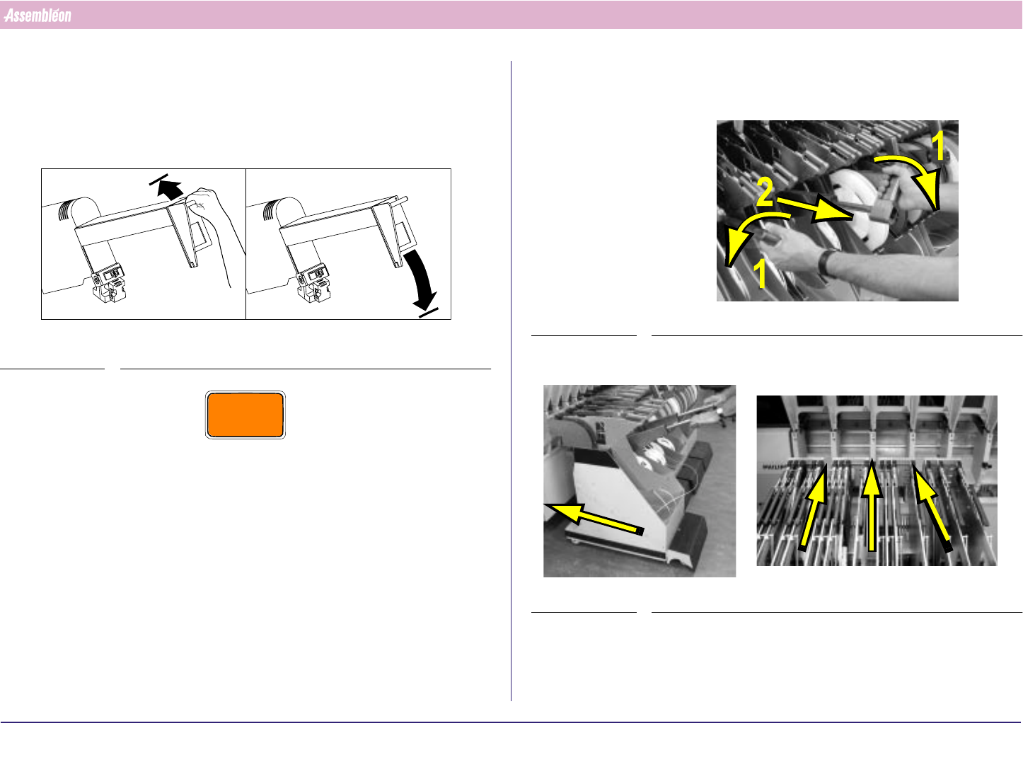
2.7.1 Lowering Placement Modules
Unlock a placement module by pushing it up and let it go down by itself.
FIGURE 10
CAUTION
DO NOT PULL DOWN THE PLACEMENT MODULE, OTHERWISE THE
LOCKING SYSTEM WILL GET DAMAGED.
A
B
2.7.2 Feeder Trolley Handling
1.
FIGURE 11
2. Roll the feeder trolley in the required position.
FIGURE 12
4022 591 96062 Operating Manual
02.02 FCM Multiflex 12
General Machine Information
3. Push both buttons until the trolley is fully lifted.
FIGURE 13
4.
FIGURE 14
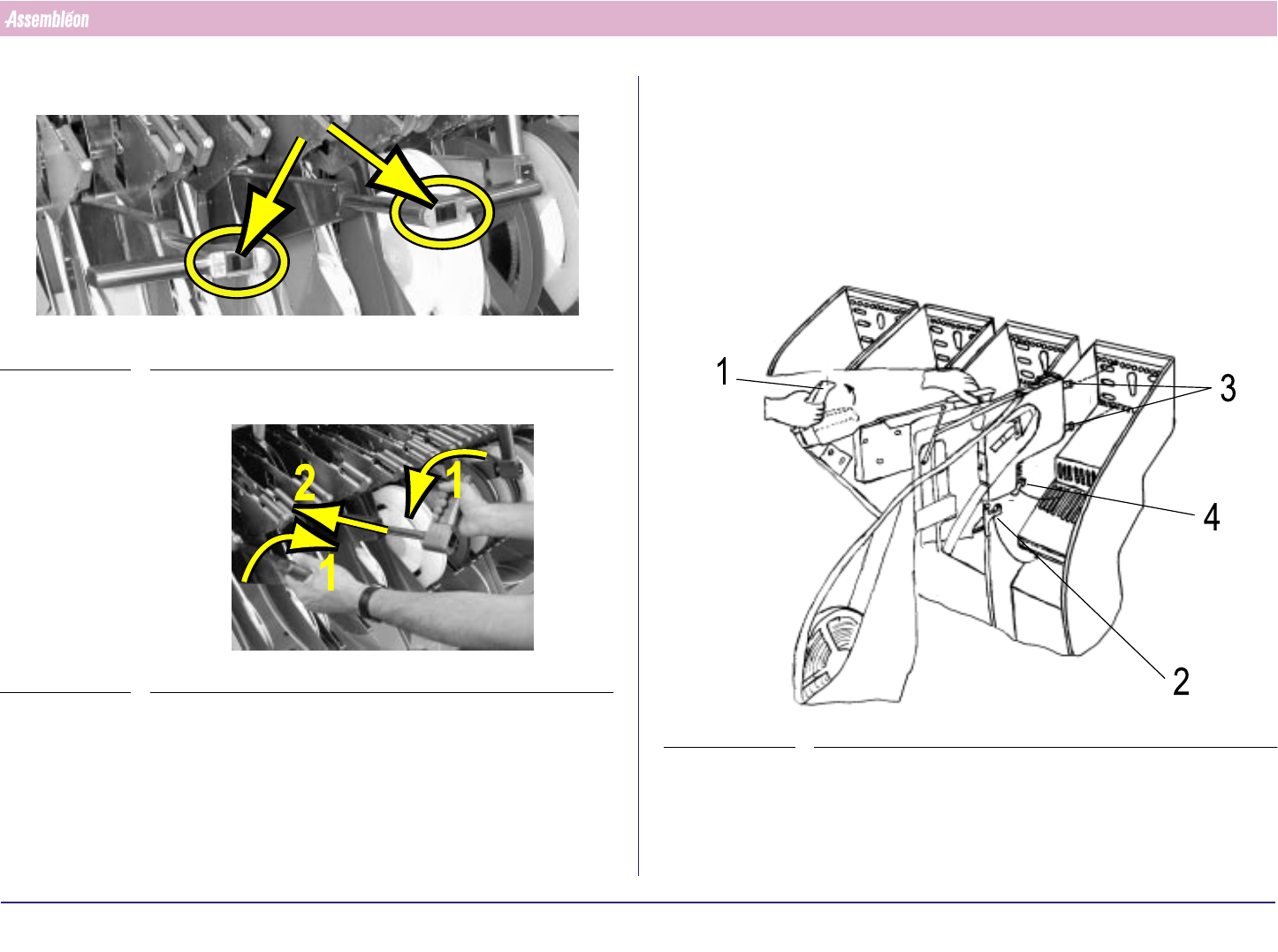
2.7.3 Feeder Handling
2.7.3.1 Feeder Exchange
1. Check if the bottom and supporting surfaces of the feeder interface of
the machine are clean and free from components and mechanical
damage.
2. Take the feeder by handle and top guide. Let the pre-guide strip (4) fall
into the slit of the feeder bar.
FIGURE 15
3. Release handle (1) and slide the two positioning-pins into the holes as
far as the clamping lever (2) locks onto the locking axis of the trolley.
Make sure that the feeder runs straight and parallel with the slit of the
feeder bar during insertion.