Operating Manual - 第52页
4022 591 960 62 Operating Manual 02.0 2 FCM Mu ltif lex 50 New Progr am Selection 11.Rem ov e the board b y pu shin g the strips outwar ds FIGURE 87 12.Pu sh the strips ba ck FIGURE 88 CLICK! CLICK! 13.Clos e th e Run- i…
4022 591 96062 Operating Manual
02.02 FCM Multiflex 49
New Program Selection
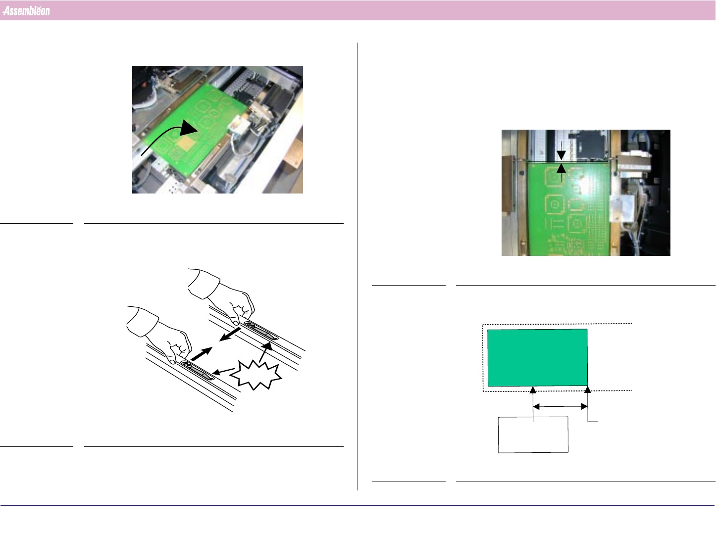
6. Place board on the first position of the first carrier
FIGURE 83
7. Push the transport guide strips back
FIGURE 84
CLICK!
8. When fixed stoppers are available on the carrier, shift the front stopper
to the most right position and remove both front and rear stopper arms
and proceed with step 10. or else with 9.
9. Adjust the stopper. Distance between the front side of the board and the
stopper must be 0.2 +/- 0.1 mm. Test the stopper by moving the arm up
an down
FIGURE 85
10.Adjust the low speed sensor
FIGURE 86
0.2
+0.1
-0
mm
First PCB on first
“carrier” position
at pick-up position
PCB stop/pick-up
position
80mm
Low Speed
sensor
4022 591 96062 Operating Manual
02.02 FCM Multiflex 50
New Program Selection
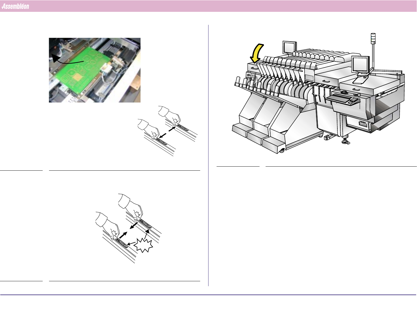
11.Remove the board by pushing the strips outwards
FIGURE 87
12.Push the strips back
FIGURE 88
CLICK!CLICK!
13.Close the Run-in Cover
FIGURE 89
4022 591 96062 Operating Manual
02.02 FCM Multiflex 51
New Program Selection
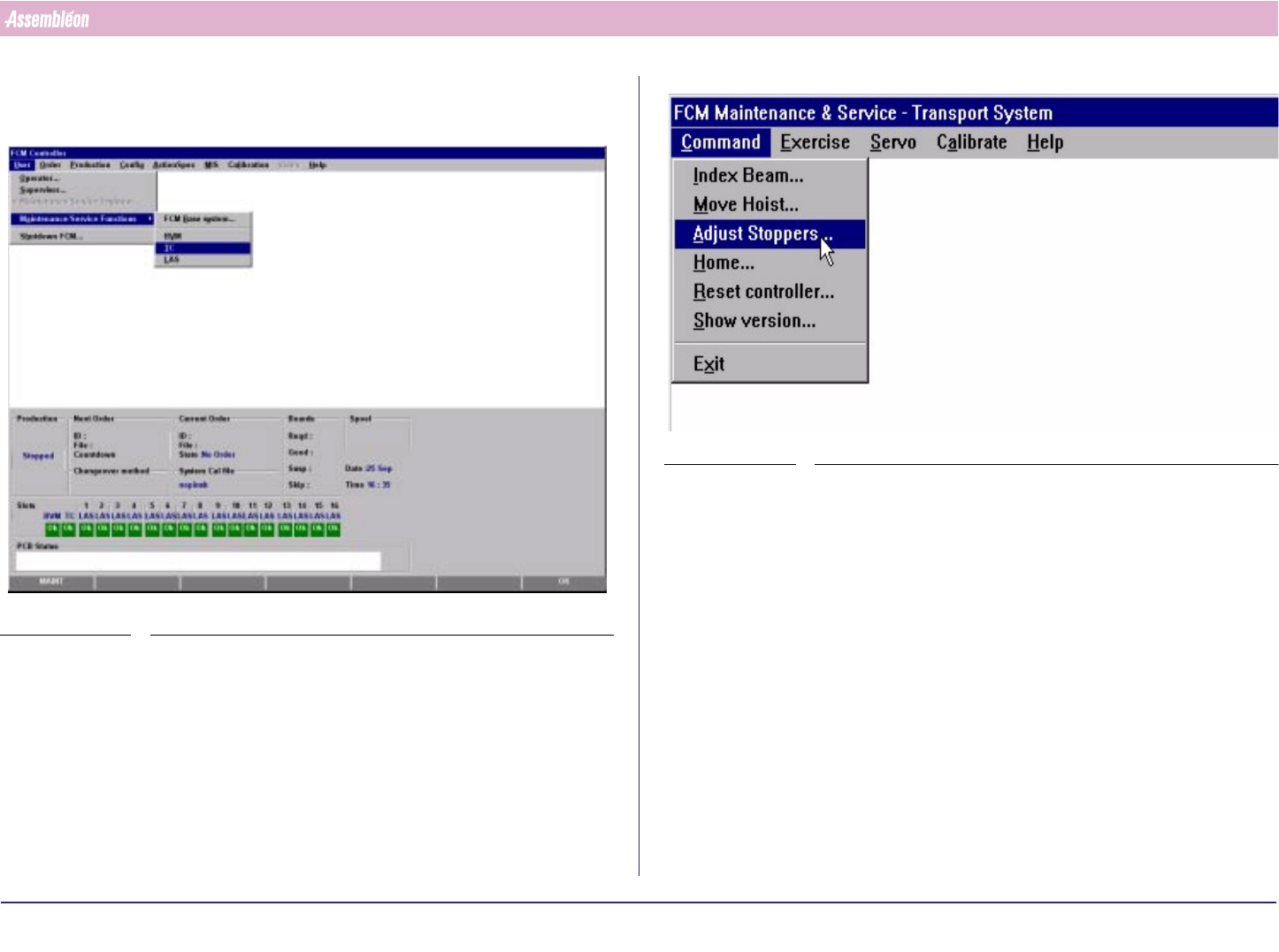
8.4.2 Run-Out Section and Anti Collision Sensor
1. Select “User” - “Maintenance/Service functions”-“TC”
SCREEN 30
2. Select “Command” - “Adjust stopper”
SCREEN 31