Operating Manual - 第54页
4022 591 960 62 Operating Manual 02.0 2 FCM Mu ltif lex 52 New Progr am Selection 3. Sel ect R un-out F9 and ho ist in “ up ” posit ion (F11) (atten tion: tr ansport start s m o ving) SCREEN 32 4. Open th e Run-out co ve…
4022 591 96062 Operating Manual
02.02 FCM Multiflex 51
New Program Selection
8.4.2 Run-Out Section and Anti Collision Sensor
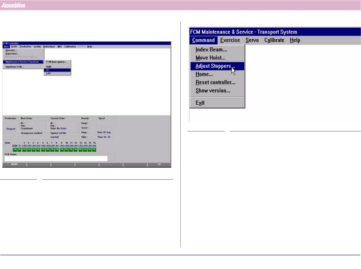
1. Select “User” - “Maintenance/Service functions”-“TC”
SCREEN 30
2. Select “Command” - “Adjust stopper”
SCREEN 31
4022 591 96062 Operating Manual
02.02 FCM Multiflex 52
New Program Selection
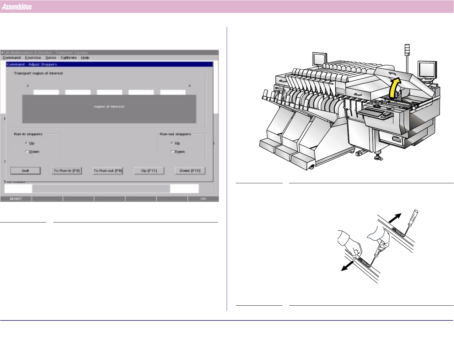
3. Select Run-out F9 and hoist in “up” position (F11) (attention: transport
starts moving)
SCREEN 32
4. Open the Run-out cover
FIGURE 90
5. Unlock the guide strips
FIGURE 91
4022 591 96062 Operating Manual
02.02 FCM Multiflex 53
New Program Selection
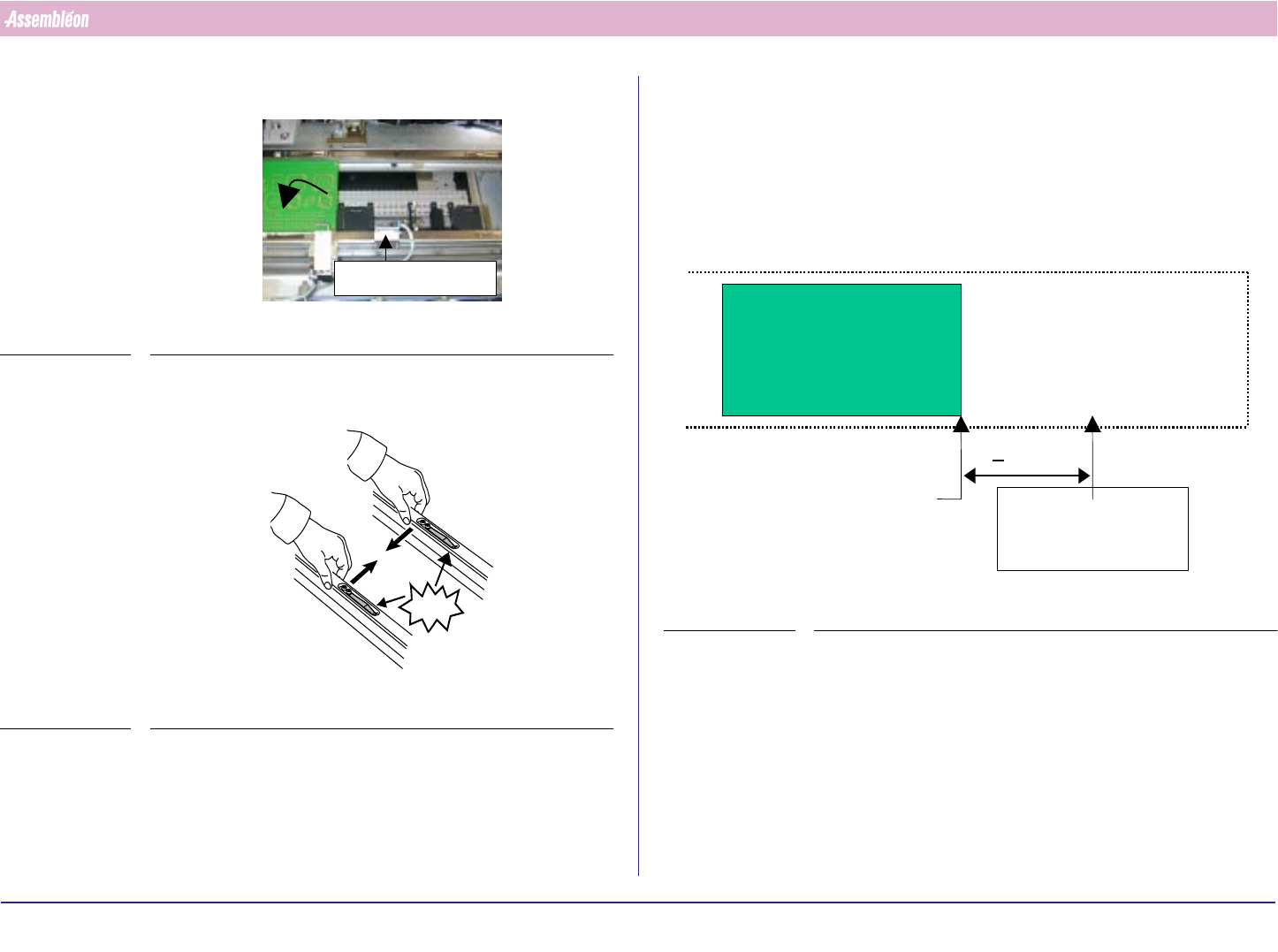
6. Place a board on the second last board position
FIGURE 92
7. Push the guides strips back
FIGURE 93
Anti collision
CLICK!
8. Check if board is positioned on Run out belt. (board-pitch 360 & 420
mm)
a) If so, then: adjust stopper so that distance between the front side of
the board and the stopper is 0.2 +/- 0.1 mm). Test the stopper by
moving the arm up an down.
b) Else: Turn the stopper arms upwards, by loosening the screws
9. Adjust the anti collision sensor
FIGURE 94
Edge of second
last PCB on X-beam
/
carrier at last index
>80mm
Anti Collision
sensor