00193279-01.pdf - 第30页
Fan wi th Incr eas ed Po wer, i ncl. A ir Fil ter Box Re trof itt ing and Ma inten ance I nstr uct ions SI PLAC E HS- 50 2. 4 R etr of it ti ng Pr oce du re Issu e 07 /01 30 F ig. 2. 4. 1 Mou nti ng th e O- rin g S ea ls…

Retrofitting and Maintenance Instructions SIPLACE HS-50 Fan with Increased Power,incl. AirFilter Box
Issue 07/01 2.4 Retrofitting Procedure
29
2.4 Retrofitting Procedure
2.4.1 Preparing Both Air Filter Boxes
Perform the following jobs in advance so that you do not need to interrupt production more than
necessary. 2
à Pick up the preassembled air filter box (Item no. see Sec. 2.2).
à Press gently against the lug on the long side of the tray (see Fig. 2.5.1) and lift the cover off
the tray of the air filter box.
NOTE:
The self adhesive Velcro strips (L = 194 and 360), Item no. see Sec. 2.2, are already stuck onto
the cover frame.
The uncovered central strut of the frame must be pointing downwards in the installation position.2
à Place the filter mat (Item no. see Sec. 2.2), which is already attached to a filter frame when
delivered, on the cover frame so it is flush with the outside edges of the frame all the way
around.
à Press the filter mat (with frame) against the Velcro strips along the outside edges.
à Also perform the steps described above for the second air filter box which you are going to
retrofit.
Fan with Increased Power, incl. Air Filter Box Retrofitting and Maintenance Instructions SIPLACE HS-50
2.4 Retrofitting Procedure Issue 07/01
30
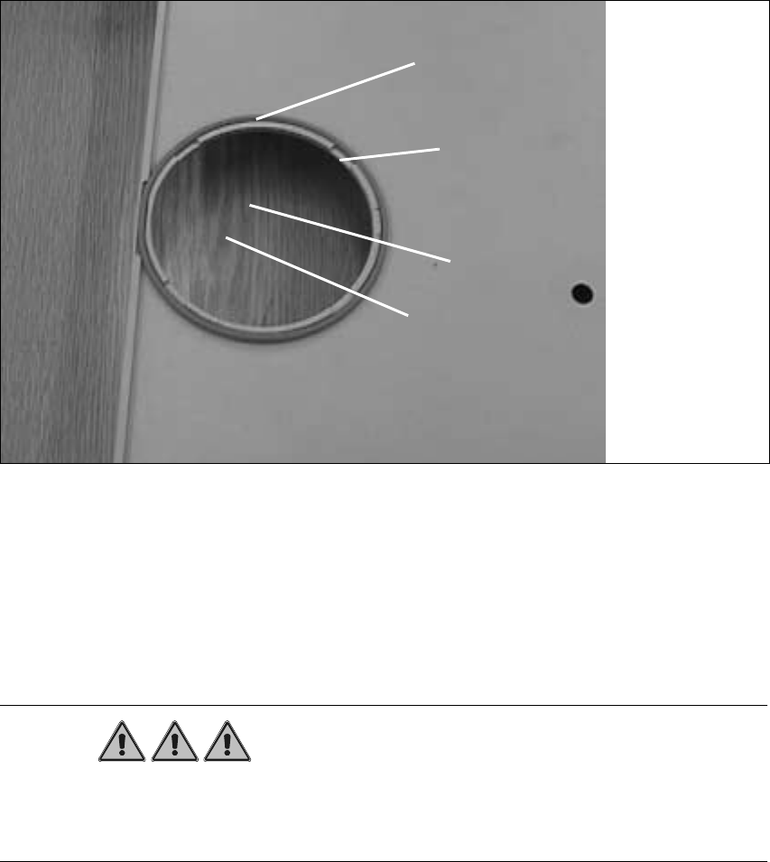
Fig. 2.4.1 Mounting the O-ring Seals on Both Perforated Collars of the Tray
à Put down the air filter box so the curved surface is pointing downwards, as shown above.
à At each circular cut-out, pull an O-ring seal (Item no. see Sec. 2.2) onto the perforated collar.
2.4.2 Switching the Machine Off
DANGER
Retrofitting is only allowed to be carried out by SMD service engineers of Siemens Dematic AG.
Comply with all of the safety instructions in Sec. 2.3.
The machine remains in the line. The component changeover table remains docked. 2
à Stop the placement sequenceat a suitable pointandshut down theoperating system Windows
NT.
à Turn the machine OFF at the main switch.
à Isolate the machine from the mains.
à During the entire retrofitting sequence, secure the machine against unauthorized reactivation
as described in the Chapter "Locking the Machine..." in the User Manual SIPLACE HS-50
à With a visual check make certain that both the fans have stopped.
Tray
O-ring seal
Perforated collar
Notched recess
Retrofitting and Maintenance Instructions SIPLACE HS-50 Fan with Increased Power,incl. AirFilter Box
Issue 07/01 2.4 Retrofitting Procedure
31
2.4.3 Installation Work on the Machine
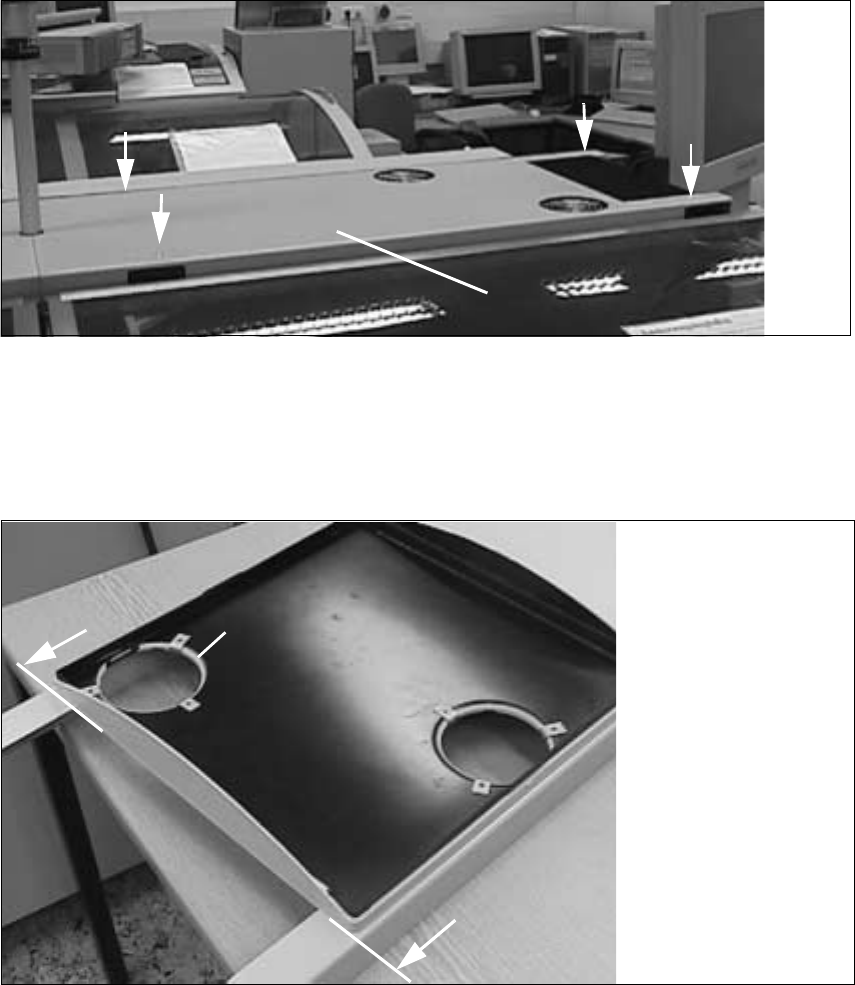
Fig. 2.4.2 Removing the Gantry Cover
à Unfasten the gantry cover (see 4 arrows): 2 oval-head screws M4 (driver 2.5 mm).
à Lift the gantry cover off the machine and place the cover on a workbench.
Fig. 2.4.3 Putting on the Tray of the Air Filter Box, Flush with the Edge of Gantry Cover
à Position the prepared tray of the air filter box on the removed gantry cover so it is flush with the
crossways plate edge of the gantry cover
(see arrows in the figure above).
In this position, the perforated collars of the tray (of the filter box) engage in the circular cut-
outs in the gantry cover.
Gantry cover
Position of
the circular cut-out