00193279-01.pdf - 第34页
Fan wi th Incr eas ed Po wer, i ncl. A ir Fil ter Box Re trof itt ing and Ma inten ance I nstr uct ions SI PLAC E HS- 50 2. 4 R etr of it ti ng Pr oce du re Issu e 07 /01 34 à Di sconnect the plug connec tions for the 4 …
Retrofitting and Maintenance Instructions SIPLACE HS-50 Fan with Increased Power,incl. AirFilter Box
Issue 07/01 2.4 Retrofitting Procedure
33
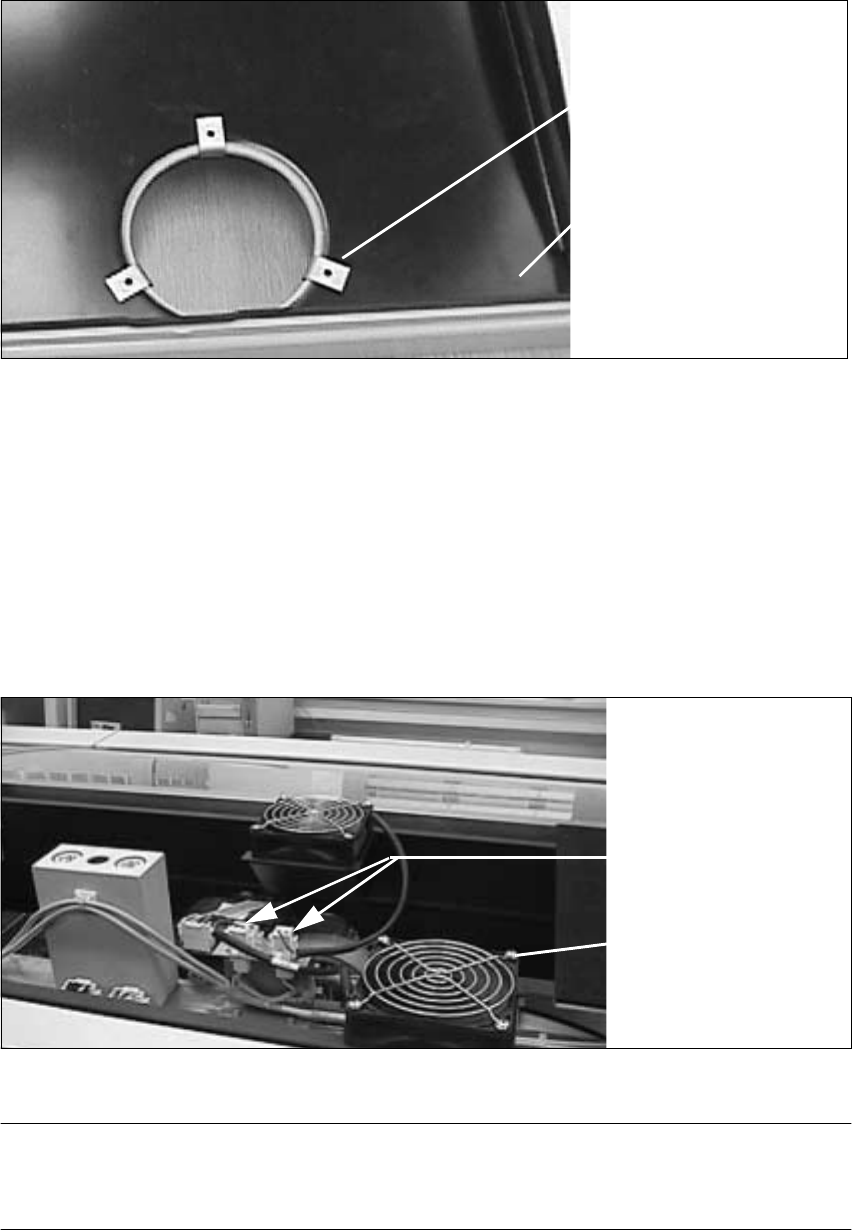
Fig. 2.4.5 Position of the Clamping Elements Around the Circular Cut-outs
à Insert 3 clamping elements (Item no. see Sec. 2.2) around each circular cut-out, spaced at an
angle of about 120 degrees in relation to one another (see figure above). Use them to clamp
the tray of the air filter box onto the gantry cover.
à Also perform the steps described above for the gantry cover on the other side.
2.4.4 Replacing the Existing 4 Fans by Fans with Increased Power
Fig. 2.4.6 Removing and Installing four Fans
NOTE:
The assignment of the 2 plugs for each of the fans, i.e. in the gantry area left or right, does not
matter. 2
Tray mounted on
3 brackets
the gantry cover
Electrical connection
Attaching the fan
Fan with Increased Power, incl. Air Filter Box Retrofitting and Maintenance Instructions SIPLACE HS-50
2.4 Retrofitting Procedure Issue 07/01
34
à Disconnect the plug connections for the 4 fan cables (see figure above).
à Unfasten the 4 fans: Each has4 oval-head screws M4 (driver 2.5 mm). Remove the protective
grilles and the fans.
à Cleantheprotectivegrillewithadampcloth.
à Insert the 4 new fans one after the other (Item no. see Sec. 2.2).
à Replace the previously removed protective grilles on the new fans and attach the fans and
grilles to the machine using the 4 oval-head screws M4 (driver 2.5 mm).
à Connect the plug connections for the 4 new fans. The plugs are keyed.
2.4.5 Fitting the Gantry Cover and Tray onto the Machine
à Place both gantry covers and the tray mounted on each onto the machine and position the
gantry cover so its outside edges are flush.
à Place one CONTACT washer each (Item no. see Sec. 2.2) to the two mounting holes on the
gantry cover which are CLOSTEST to the flat screen (see Fig. 2.4.7 and Fig. 2.1.1).
à Attach the gantry cover with the 4 oval-head screws M4 (driver 2.5 mm) retained from when
the cover was removed.
2.4.6 Inserting the Covers for the Two Air Filter Boxes
Fig. 2.4.7 Clipping the Cover into the Tray of the air Filter Box
à Make certain:
The filter frame with the filter mat is already attached to the Velcro strip of the cover frame.
The uncovered brace of the filter frame is pointing downwards.
Retrofitting and Maintenance Instructions SIPLACE HS-50 Fan with Increased Power,incl. AirFilter Box
Issue 07/01 2.4 Retrofitting Procedure
35
à Apply slight pressure from above to put the "cover assembly" (incl. the filter mat) onto the
corresponding tray and clip the cover into the tray as you do so.
This completes the mounting of the air filter box and the machine is once again ready to
operate.
à Remove all tools, etc. from the machine.
à Switch ON the machine. Per visual check make certain that each of the 4 fans are rotating.
It is also possible to check they are drawing in air by holding a piece of paper briefly near the
cover on the outside.