DEK INFINITY USER MANUAL.pdf.pdf - 第140页
INFINITY 6(735()(5(1 &(6 35()(5(1&(6 2.14 User Manual Software Versi on 7 Paste T rails Provides the capab ility to reduce solder paste trails from squeegees autom ati- cally , options are: If mode 1 is selected…

INFINITY
6(735()(5(1&(6
35()(5(1&(6
Software Version 7 User Manual 2.13
Vortex Under Screen
Cleaner
To enable the Vortex under screen cleaner carry out the following:
1. Press the function key F10 on the keyboard, a window of the following form
is displayed:
NOTE
If the blue under screen cleaner is currently enabled, carry out disabling the
blue under screen cleaner first.
2. Type vorton using the keyboard.
3. Press Enter, the message ‘Vortex Under-Screen Cleaner Enabled ’is
displayed in the message prompt bar.
The Vortex under screen cleaner becomes the current cleaner and all cleaner
parameters become appropriate to the Vortex cleaner.
The value of the configuration parameter cleaner type is set to Vortex and
this parameter is written to the configuration file.
4. Press Exit.
1. Press the function key F10 on the keyboard, a window of the following form
is displayed:
2. Type vortoff using the keyboard.
3. Press Enter, the message Vortex Under-Screen Cleaner Disabled is dis-
played in the message prompt bar.
The silver under screen cleaner becomes the current cleaner and all cleaner
parameters revert to being appropriate to the previous cleaner.
The value of the configuration parameter cleaner type is set to silver and this
parameter is written to the configuration file.
4. Press Exit.
<Enter> to Close ...
Serial Number
Executable date
Executable time
Executable name
Software Version
Options Enabled
:
:
:
:
:
:
201305
March 19 2000
10:57:38
RR0400.EXE
05.00
SBNG
INFINITY
<Enter> to Close ...
Serial Number
Executable date
Executable time
Executable name
Software Version
Options Enabled
:
:
:
:
:
:
201305
March 19 2000
10:57:38
RR0400.EXE
05.00
SBNG
INFINITY
INFINITY
6(735()(5(1&(6
35()(5(1&(6
2.14 User Manual Software Version 7
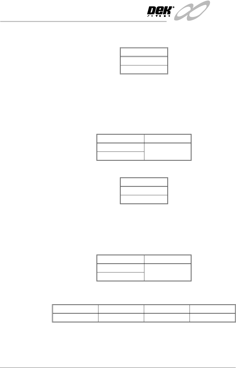
Paste Trails Provides the capability to reduce solder paste trails from squeegees automati-
cally, options are:
If mode 1 is selected, any paste that has dripped from the squeegee is scooped
up, by the squeegee back to the paste roll. This process occurs at the start of
every stroke, with the print mode set to print/print and at the start of only the
print stroke, when the print mode is set to flood/print or print/flood.
Transport Wait
Mode
This option enables the product to be held in contact with the screen until both
upline and downline systems are ready to transfer, options are:
Clamp Type Sets the type of board clamp used, options are:
To eliminate vacuum seal loss during alignment, if the Snuggers option is
selected and the tooling type is Vacuum, the rails do not dip when the camera is
traversing.
On the Fly Sets whether the camera captures fiducials whilst moving over them (on the fly),
or whether the camera stops over the fiducial first, options are:
Snugger Thickness This parameter is only available if snuggers has been selected from the Clamp
Type preference, the options are:
Options
Disabled
Mode 1
Options Default
Standard Standard
Hold_at_Print
Options
Board Clamp
Snuggers
Options Default
Enabled Disabled
Disabled
Minimum Maximum Increment Default
0.8mm 2.0mm 0.1mm 1.6mm
INFINITY
6(735()(5(1&(6
35()(5(1&(6
Software Version 7 User Manual 2.15
Tooling Monitoring This parameter sets, while Feature Licensing asserts that use of Tooling Devia-
tion Monitoring is authorized, the frequency (in boards printed) at which moni-
toring is performed. Monitoring is also carried out on the first print stroke of a
print run.
This feature only applies while squeegees are fitted.
When a particular print stroke is being monitored, as the squeegee traverses the
image the pressure being applied is measured and recorded. Any variations in
the load being applied, as a result of insufficient tooling support or underside
components coming into contact with the tooling are noted. Upon completion
of the print stroke, the deviation in the pressure applied over the print stroke is
determined and expressed as the tooling deviation. The tooling deviation is
calculated from the minimum and maximum values and expressed as a percent-
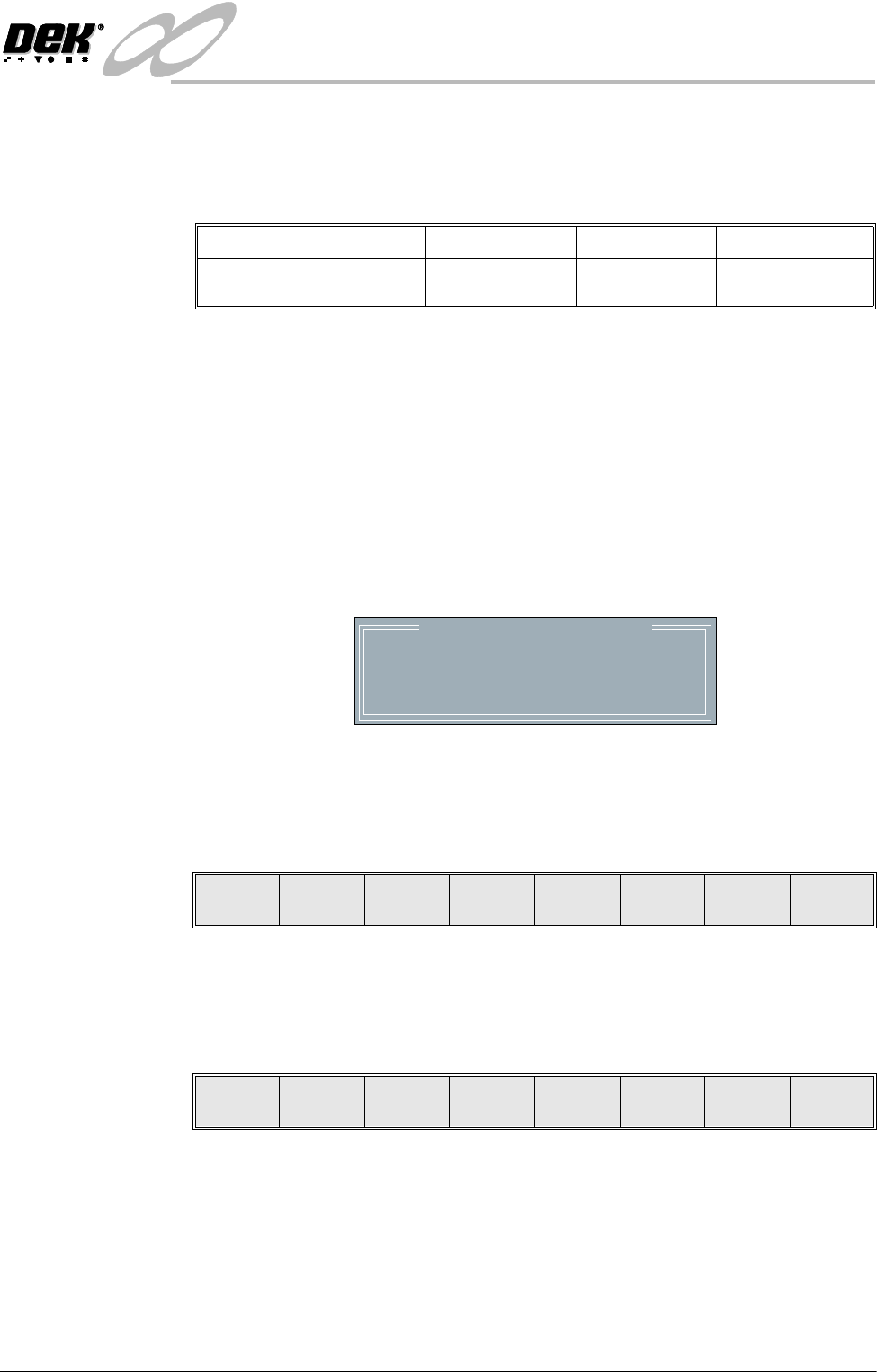
age. If the tooling deviation exceeds the permitted threshold, as set by the
Tooling Deviation parameter in the product file, a cyclic log text file called
deviate.dat is written and the following window is displayed:
NOTE
The number of samples is the amount of pressure variations recorded during the
print stroke.
The following menu bar is displayed:
On selecting Continue printing proceeds until it is interrupted by some other
cause.
On selecting Abort printing is discontinued and the following menu bar is
displayed, to enable the board to be removed from the machine:
If the number of samples (pressure variations) during a print stroke is less than
2 or the minimum value is zero, the error message ‘Failed to determine Tooling
Deviation’ is displayed.
Minimum Maximum Increment Default
0 Boards
(Tooling Monitor Disabled)
200 Boards 1 0 Boards
Excessive Tooling Deviation
Tooling Deviation : 25.08 %
Number of Samples : 81
Check the Board Support.
Continue Abort
Auto
Board
Manual
Board
Exit