DEK INFINITY USER MANUAL.pdf.pdf - 第148页
INFINITY 6(735()(5(1 &(6 35()(5(1&(6 2.22 User Manual Software Versi on 7 The four adjustable parameter s have the following ranges: NOTE The faster the baud rate the faster informati on transfer occurs. SPC dat…
INFINITY
6(735()(5(1&(6
35()(5(1&(6
Software Version 7 User Manual 2.21
With Unload Board Start highlighted, selecting either Incr. or Decr. to change
the parameter to Separation displays the following window and menu bar:
The Continue Change key closes the warning window and the Unload Board
Start event is recorded.
The Reset To Trans key closes the warning window and the Unload Board Start
is set to Transport.
SPC Port
Configuration
This preference allows the user to set the configuration of the SPC port output
rate and data format.
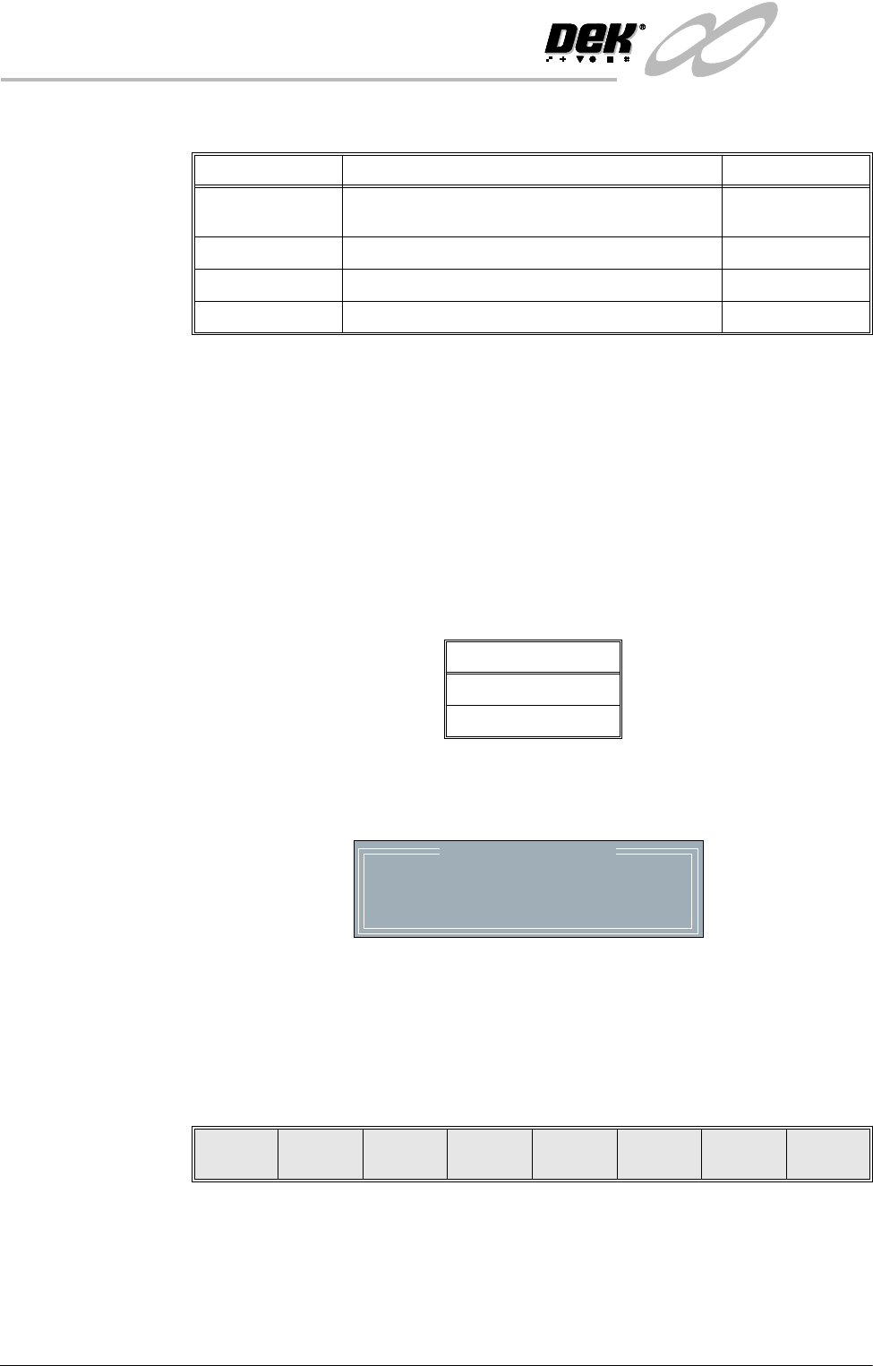
Selecting the Incr. or Decr. buttons whilst this preference is highlighted opens
a further parameter window.
The menu bar changes to:
The Next and Previous keys move the cursor between the parameters.
The Incr. and Decr. keys change the value of the highlighted parameter.
The Exit key returns to the set preferences menu.
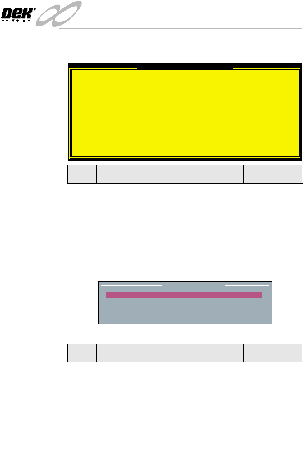
Unload Board Speedup Warning
The UNLOAD BOARD SPEEDUP option is set to
'Separation'
With this option enabled it should be noted
that there is only a minimal clearance
between the underside of the board and any
tooling being used, while the board is being
unloaded.
This option must not be used for boards that
are populated on the underside, as this
could damage the boards.
This option cannot be used with HTC
printers.
Continue
Change
Reset
To Trans.
SPC CONFIGURATION
BAUD RATE
WORD LENGTH
PARITY
STOP BITS
:
:
:
:
38400
8
None
1
Next Previous Incr. Decr. Exit
INFINITY
6(735()(5(1&(6
35()(5(1&(6
2.22 User Manual Software Version 7
The four adjustable parameters have the following ranges:
NOTE
The faster the baud rate the faster information transfer occurs.
SPC data is output when any of the following occur:
• SPC output cycle (as per Output Rate)
• Alignment Inspection Cycle
• 2D Inspection Cycle
Maint. Monitoring This preference, when enabled, provides an indication to the operator when a
preventive maintenance service is due. Options are:
When enabled, if Run (F1) is pressed on the menu bar and a service is due, the
amber light on the tricolour beacon is illuminated. The following window is
displayed:
The message in the window varies dependent upon the type of service due. If a
period of one month or 45,000 cycles has elapsed, the message is as shown
above. If a period of six months or 260,000 cycles has elapsed, the message is
‘Six Monthly service is due’. If a period of one year or 520,000 cycles has
elapsed, the message is ‘Yearly service is due’.
The menu bar changes to the following:
Parameter Options Default
Baud Rate 110, 300, 600, 1200, 2400, 3600, 4800, 9600,
14400, 19200, 28800, 38400
9600
Word Length 5, 6, 7, 8 8
Parity ODD, EVEN, NONE, MARK, SPACE NONE
Stop Bits 1,2 1
Options
Enabled
Disabled
Maintenance Monitor
Monthly service is due
Done Defer

INFINITY
6(735()(5(1&(6
35()(5(1&(6
Software Version 7 User Manual 2.23
The Done key updates the maintenance monitor data file, named service.dat, as
follows:
• The service cycle counter is set to zero.
• The service number is incremented.
• The last service date is reset to the current date.
• The warning window is cleared, the amber beacon changes to green and the
printing run commences.
The Defer key does not update the maintenance monitor data file.
The warning window is cleared, the amber beacon changes to green and the
printing run commences. As the file has not been updated, the next time the Run
key is pressed the maintenance monitor window is displayed again. This routine
continues until the Done key is pressed.
If Maintenance Monitoring is disabled, left disabled for several service periods,
either calendar or cycle or both, and enabled again:
The next time Run is pressed, the maintenance monitor software determines how
many service periods have been exceeded. From this information it determines
if any higher order servicing has been missed during the disabled period. If a
higher order service would have become due during the disabled period, that
service message is displayed.
Machine Location This allows the operator to enter text to uniquely identify the machine. Output
is via GEM, Host and SPC.
Data File Locations Allows the user to create individual directories for product and data files. Once
created the individual directories become the current locations for all future
product and data files.
Before changing the product and data file locations, use the copy data function
in House Keeping, to copy any existing product and data files to floppy disk.
After changing the product and data file locations, use the copy data function in
House Keeping, to copy any existing product and data files from the floppy disk
to the new directories.
NOTE
When Load Data is selected from the setup menu only the files in the current
location are displayed.
The default location is:
D:\Program Files\DEK\MachineControl\Printer
Selecting the Incr. or Decr. key with data file locations highlighted opens the
following window:
File Locations
Product Directory
Data Directory
:
:
D:\Program Files\Dek\MachineControl\Printer
D:\Program Files\Dek\MachineControl\Printer