DEK INFINITY USER MANUAL.pdf.pdf - 第247页
INFINITY ',163(& 7,21 02'8/( 29(59,(: Soft ware Ver sion 7 User Manual 8.7 Inspection Cycl es During setup, sites are given a priority of either Every Cycle ( EC) or General (G). The amount of sites insp…
INFINIT
Y
',163(&7,21
02'8/(29(59,(:
8.6 User Manual Software Version 7
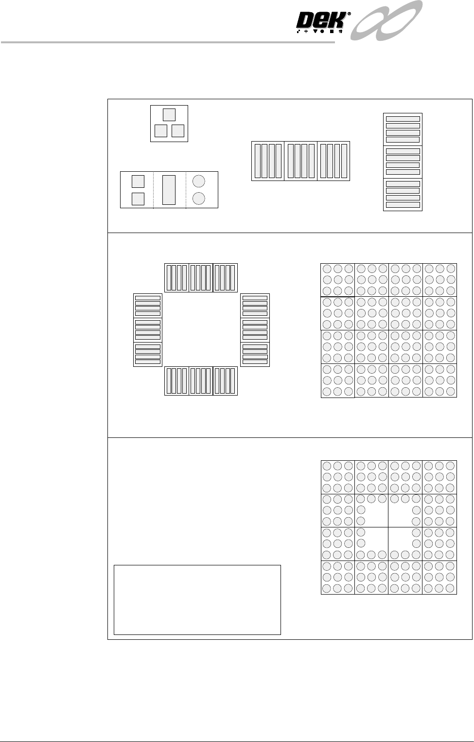
Auto Learn 2Di inspection can automatically learn different types of features as shown
below.
Figure 8-2 Auto Learn Site Types
Column of Sites
QFP
BGA
Single Site
Single Site Combination
Row of Sites
Site 1
2
3
Site 1
2
3
Site 1
2
3
4
5
6
7
8
9
10
11
12
Site 1
2
3
4
5
9
12
13
16
15
14
8
NOTE
When auto learning a component,
setup Site 1.
The component is learnt in the
sequences shown above, if the machine
is set to the correct reference.
BGA Frame
Site 1
2
3
4
16
6
14
7
8
13
5
12
15
11
10
9
INFINITY
',163(&7,21
02'8/(29(59,(:
Software Version 7 User Manual 8.7
Inspection Cycles During setup, sites are given a priority of either Every Cycle (EC) or General
(G). The amount of sites inspected during each cycle is set using the min sites/
cycle parameter, this must be set to at least the amount of every cycle sites. As
the name suggests, EC sites are inspected every cycle. General sites are
inspected depending on the value of the min sites/cycle parameter and the
number of EC sites as follows:
Number of general sites inspected per cycle = Min sites/cycle parameter - EC
sites.
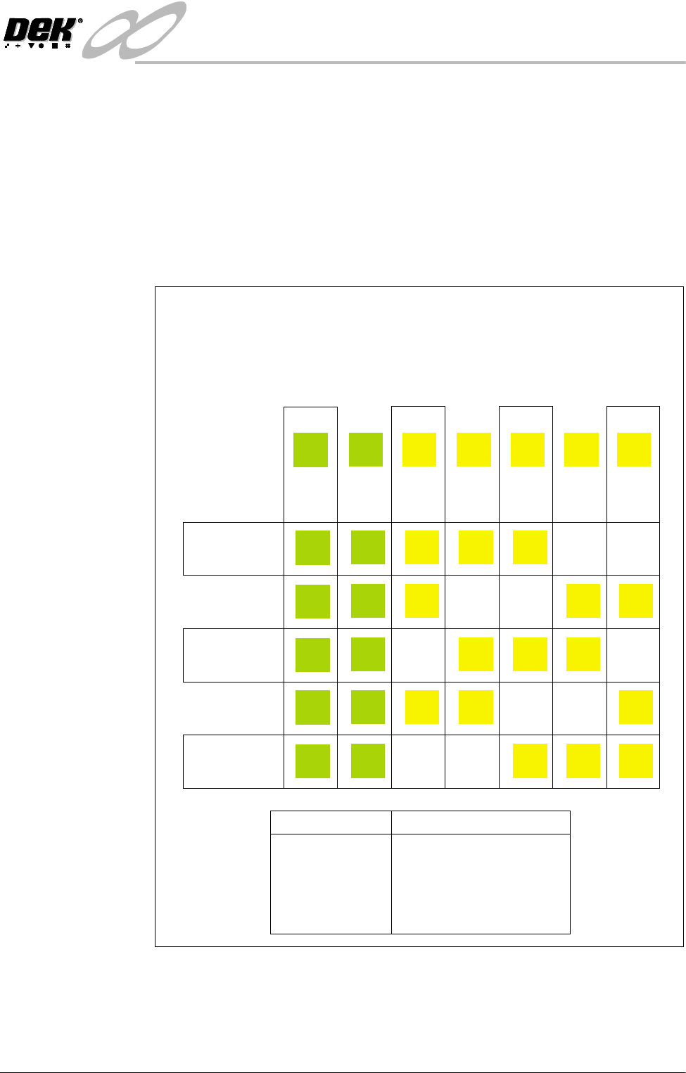
The general sites are inspected in rotation as shown below.
Figure 8-3 Site Inspection Cycles
min sites / cycle = 5
Cycle 1
Cycle 2
Cycle 3
Cycle 4
Cycle 5
In the example below, seven sites have been setup, with two given the priority
of and five given the priority of .
The min sites/cycle parameter is set at 5. As there are two EC sites, this leaves
three G sites to be inspected at each cycle as shown.
Every Cycle (EC) General (G)
Site 1
EC
EC
EC
EC
EC
EC
Site 2
EC
EC
EC
EC
EC
EC
Site 3
G
G
G
G
Site 4
G
G
G
G
Site 5
G
G
G
G
Site 6
G
G
G
G
Site 7
G
G
G
G
SITES
Cycle 1
Cycle 2
Cycle 3
Cycle 4
Cycle 5
Cycle 6
3, 4, 5
6, 7, 3
4, 5, 6
7, 3, 4
5, 6, 7
process repeats
INFINIT
Y
',163(&7,21
02'8/(29(59,(:
8.8 User Manual Software Version 7
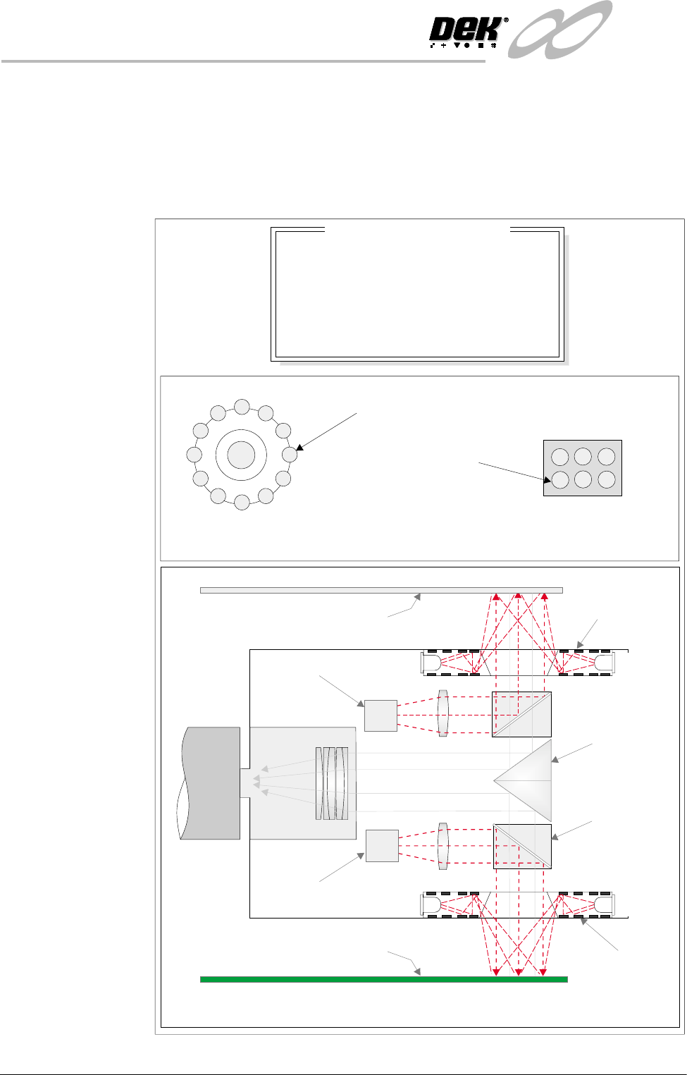
Lighting The lighting levels for 2D inspection is software controlled. For a more detailed
description of the camera and optical unit refer to the Technical Reference
Manual, Camera and Vision Systems Module Chapter.
The green camera lighting parameters and functions are shown below. Each
lighting group can be set by the operator to a level between 0 to 15, where 15 is
the brightest.
Figure 8-4 Software Controlled Lighting - Green Camera
Oblique Lighting LED
Board and Stencil Lighting LED Configurations
Adjustable iIlumination of Board and Stencil
Direct Lighting LED
Plan ViewPlan View
8
8
8
8
-1.0
-1.5
2.0
2.0
Inspection Lighting Parameters
Screen Vertical
Screen Oblique
Board Vertical
Board Oblique
Window Left
Window Top
Window Width
Window Height
mm
mm
mm
mm
Underside Stencil
Board
Prism
Beam Splitter
Cube
Oblique
Lighting
Oblique
Lighting
Direct Lighting
Direct Lighting
Camera