DEK INFINITY USER MANUAL.pdf.pdf - 第251页
INFINITY ',163(& 7,21 02'8/( 29(59,(: Soft ware Ver sion 7 User Manual 8.11 Graphical User Interface (GUI) 2D inspection uti lizes a Graphica l User In terface (GUI) allowing inspe ction sites to be set …
INFINIT
Y
',163(&7,21
02'8/(29(59,(:
8.10 User Manual Software Version 7
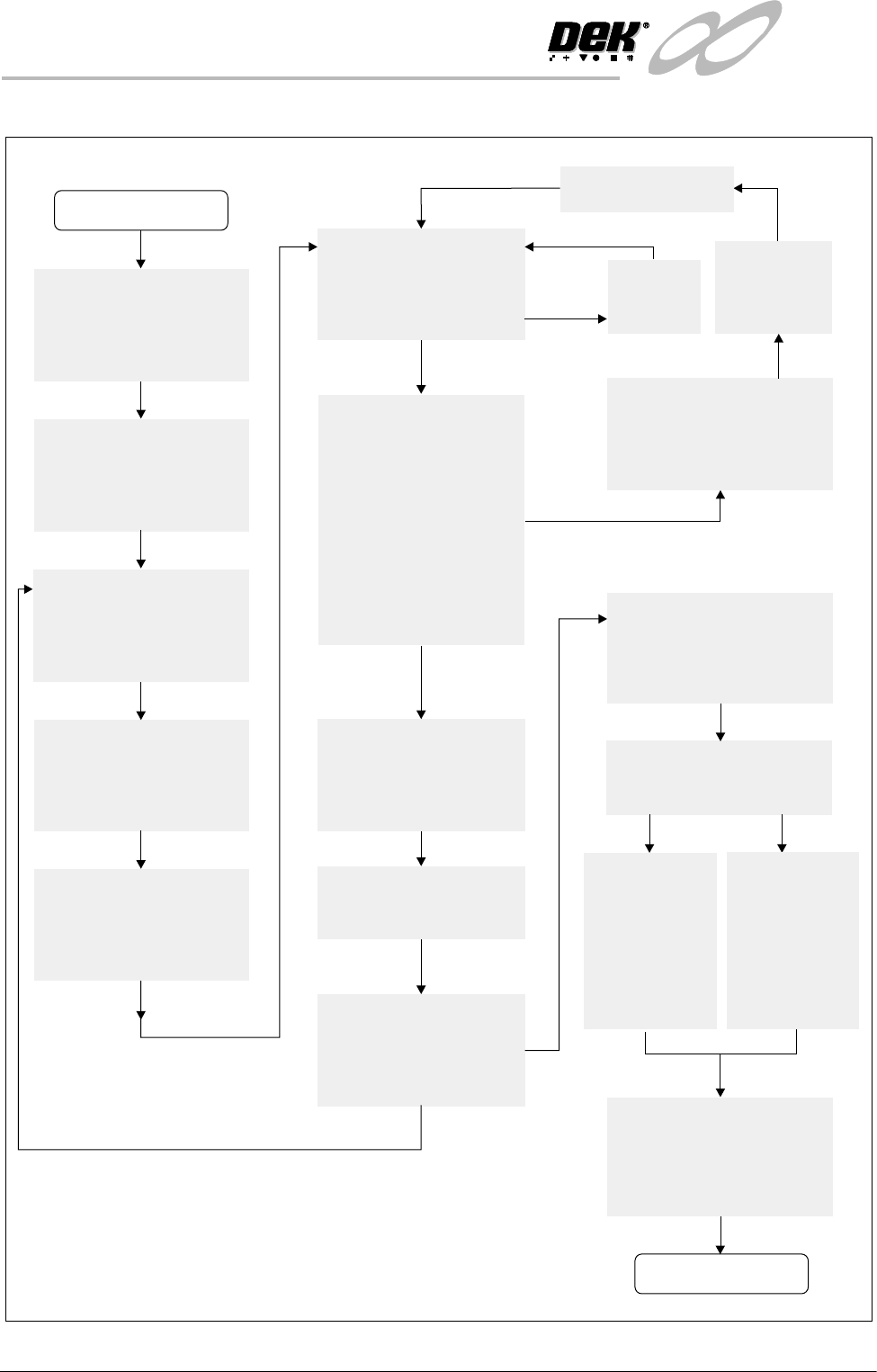
Figure 8-6 2D Inspection Setup Guide
Adjust Lighting:
Adjust so all board pads are
white with sharp edges and
the screen is seen clearly.
Add Limits Sets:
Set wide tolerances so no
alarms occur.
Add Site:
Name, Location Etc
Ensure all pads are within
the search box.
Set Globals as required:
Board and Stencil Inspect
Types etc.
Learn Site / Learn Board:
Adjust board graphic ‘X’
and ‘Y’ accurately
START
Exit out
Auto Scale:
Determine the print closest
to 100% and auto scale on
that pad
Inspect Site:
Paste present data for
all pads are close to
the same value ?
If Board Inspect Type
set to Advanced,
all the paste toggles
white or yellow on the
board ?
More Sites to Teach ?
Add the rest of the sites
using the same light
settings as this first one
NO
NO
NO
NO
YES
YES
YES
YES
Print Board:
Step through the cycle
until a board is printed.
Is it a good print ?
Exit out
Place a clean
board into the
machine.
Clean stencil
Re-adjust Lighting:
Adjust the LED’s to balance
the lighting
Run Product:
Have QC Calc ?
Reset the Globals:
Set the min sites/cycle.
Set 2D Inspect Rate.
Re-adjust the Limit Sets:
The customer may have to
adjust these settings a few
times until the proper
values are found.
SPC Data:
Collect SPC
data on the
2Di. From
this data
derive the
proper ‘limit
sets’ settings.
Trial & Error:
Increase the
‘limit sets’ and
use the data
when it alarms
to derive the
proper
settings.
DONE
New Pre-image taken
INFINITY
',163(&7,21
02'8/(29(59,(:
Software Version 7 User Manual 8.11
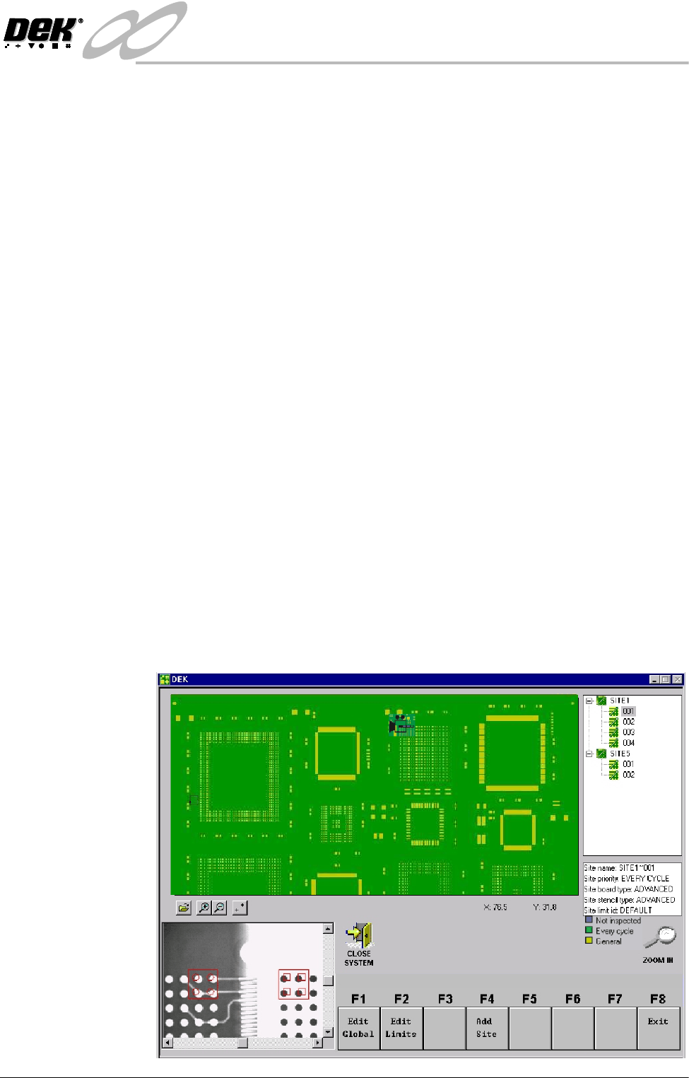
Graphical User Interface (GUI)
2D inspection utilizes a Graphical User Interface (GUI) allowing inspection
sites to be set up quickly and easily.
The 2Di GUI screen is displayed when Inspect Setup is selected on the menu
bar. The GUI provides the user with the following functions:
• A graphical representation of the board to be set up.
• Site Priority colour coding.
• Operations Buttons.
• List of inspection devices and sites.
• List of programmed site parameters.
• Current X and Y mouse coordinates.
• Vision window of board and stencil.
• Camera view adjustable using vision window scroll bars (when available).
NOTE
Refer to GUI 2Di Interface figure and table further in this section.
Representation of
Board
Two types of board image files are available for displaying the product on the
GUI board representation screen:
• Bitmap file (.bmp)
• Extended Gerber file data (.gbx)
To display the board representation in bitmap or gerber file format, the relevant
.bmp/.gbx information must be pre-loaded into the machine PC. The image is
scaled to fit the representation of the board on display, (example of gerber file
import shown below).
INFINIT
Y
',163(&7,21
02'8/(29(59,(:
8.12 User Manual Software Version 7
If no image files are available, the display defaults to a standard board size
representation of the product file being printed.
By utilizing the mouse control or touchscreen (if available), any area of the
board representation selected by the user roughly positions the camera to this
area. Fine positioning is then carried out by adjusting the X and Y scroll bars in
the vision window. Existing sites can easily be selected and adjusted using the
mouse control and touchscreen (if available).
NOTE
The vision window X and Y scroll bars are displayed only when movement of the
camera is allowed within GUI.
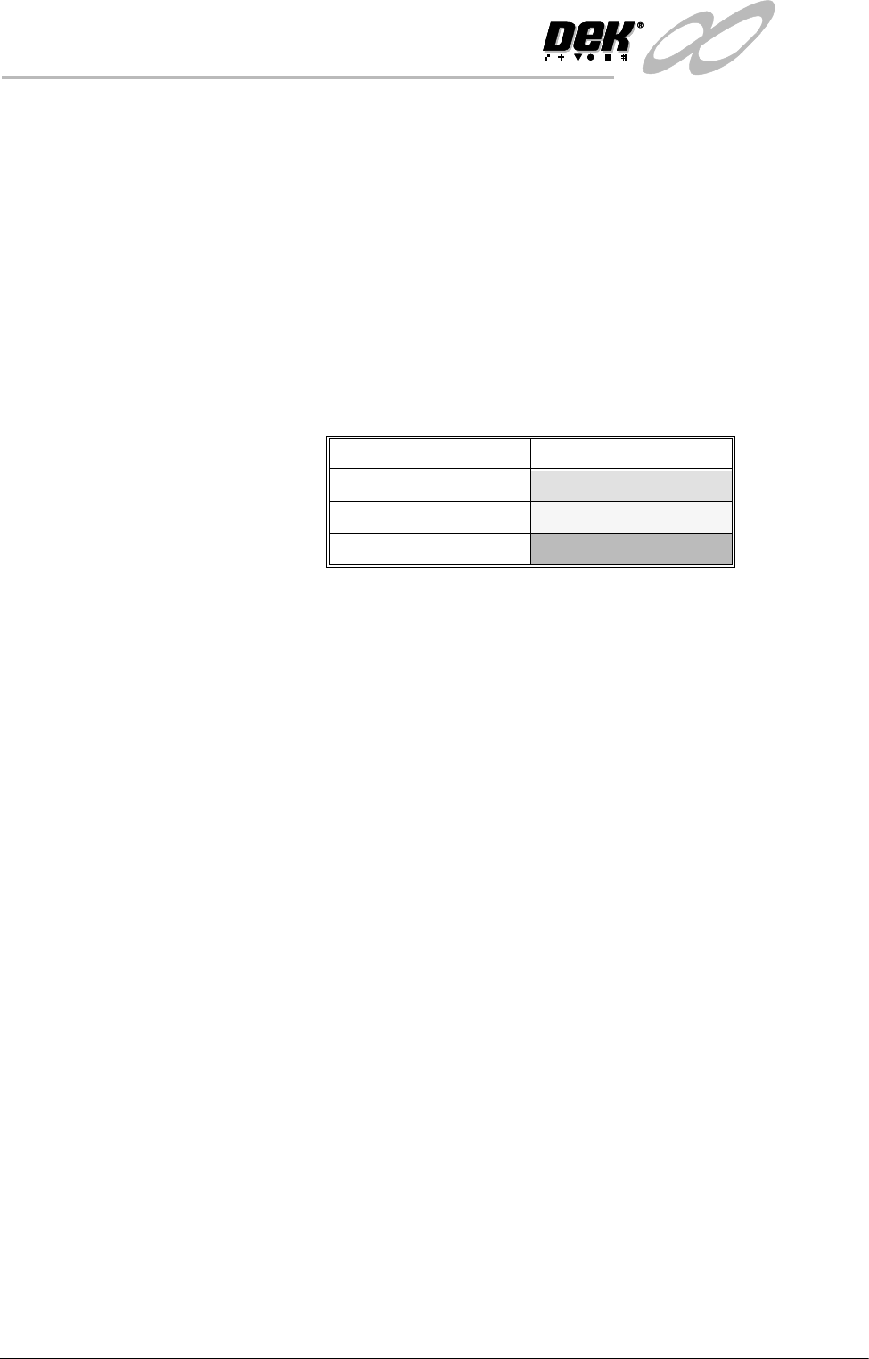
Site Colour Coding Sites displayed on the board representation are coloured according to their site
priority parameter setting, as detailed in the following table.
NOTE
The current selected site is displayed in black.
Operations Buttons The four operations buttons are sited underneath the representation of the board
and are used to perform functions on the board. These are:
• Open Image File - allows user to browse and select .bmp/.gbx image file.
• Zoom In - zooms in to sites on the board representation.
• Zoom Out - zooms out from sites on the board representation.
• Fiducial Positions - show/hides board fiducial positions.
List of Devices and
Sites
The list of devices and sites created are displayed in an expandable and
collapsible form.
By selecting a site in the list, the camera moves to that site position and the board
representation site is highlighted with a camera position icon.
By selecting a device in the list, the device list automatically expands to show
all sites within that device. The first site within the list is selected and the camera
moves to that site position, the board representation site is highlighted with a
camera position icon.
NOTE
In this instance a device itself can never be selected.
Site Parameters The site parameters window enables the user to view the editable parameters for
the current site selected.
NOTE
The parameters in this display are view only.
X and Y Site
Coordinates
The X and Y site coordinates display is the current position of the mouse pointer
on the board.
Site Priority Display Colour
Every Cycle
Green
General
Yellow
Not Inspected
Blue