DEK INFINITY USER MANUAL.pdf.pdf - 第256页
INFINIT Y ',163(&7,21 ',163(&7,21 6(78 3 8.16 User Manual Software Versi on 7 5. If the product name is cha nged the message ‘ Do you also want to create a copy of the insp ection file? ’ is displa…
INFINITY
',163(&7,21
',163(&7,216(783
Software Version 7 User Manual 8.15
4. Select Load.
5. Select Exit. The machine loads the product file and trains the fiducials.
Edit Data 1. If the loaded product file is the correct one, go to Step 9. If the file needs to
be modified continue with Step 2.
2. Select Setup.
3. Select Edit Data.
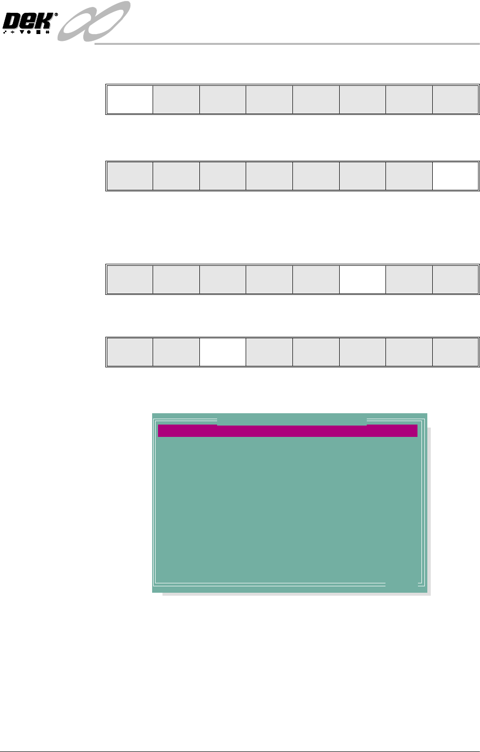
The following window is displayed:
4. To change the product name; highlight product name using the Next and
Previous keys. Select Incr. Type in the required product name and press
Enter using the keyboard.
Load
Rebuild
List
Left Right Up Down Exit
Load
Rebuild
List
Left Right Up Down Exit
Run
Open
Cover
Paste
Load
Clean
Screen
Adjust Setup Monitor Maint.
Mode
Load
Data
Edit
Data
Setup
Squeegee
Change
Screen
Change
Tooling
Change
Language
Exit
PRODUCT NAME
PRODUCT ID
DWELL HEIGHT
DWELL SPEED
SCREEN ADAPTOR
SCREEN IMAGE
CUSTOM SCREEN
BOARD WIDTH
BOARD LENGTH
BOARD THICKNESS
FRONT PRINT SPEED
REAR PRINT SPEED
FLOOD SPEED
PRINT FRONT LIMIT
Dek04
Dek04
30
24
NONE
EDGE
DISABLED
101.5
152.5
1.6
150
150
20
0.0
mm
mm/s
mm
mm
mm
mm/s
mm/s
mm/s
mm
.. more
Edit Current Process Parameters
INFINIT
Y
',163(&7,21
',163(&7,216(783
8.16 User Manual Software Version 7
5. If the product name is changed the message ‘Do you also want to create a
copy of the inspection file?’ is displayed. Select one of the following:
Yes - All data is copied, including the sites coordinates.
Global Only - The global parameters and limits are copied.
No - No inspection file is copied. Use when setting up an inspection file for
the first time.
6. Using the Next, Previous, Incr. and Decr. keys, edit the current process
parameters for the new product.
7. Press Save.
8. When the message ‘Board Data File Saved’ is displayed, press Exit.
9. Select Mode until Step appears in mode option of the printer status display.
If the required stencil is already in the printer go to Step 16.
If the stencil needs to be changed continue with Step 9.
10.Select Change Screen.
11. When the message ‘Open Front Cover and Remove screen’ is displayed
lift the printhead cover.
12.Remove the stencil from the printer.
13.Fit the new stencil into the printer ensuring the correct orientation of the
stencil.
14.Lower the printhead cover.
15.Press the System button.
Yes
Global
Only
No
Save Next Previous Incr. Decr. Exit
Save Next Previous Incr. Decr. Exit
Save Next Previous Incr. Decr. Exit
Mode
Load
Data
Edit
Data
Setup
Squeegee
Change
Screen
Change
Tooling
Change
Language
Exit
Mode
Load
Data
Edit
Data
Setup
Squeegee
Change
Screen
Change
Tooling
Change
Language
Exit
INFINITY
',163(&7,21
',163(&7,216(783
Software Version 7 User Manual 8.17
16.Select Change Screen.
17.Select Exit.
18.Select Run.
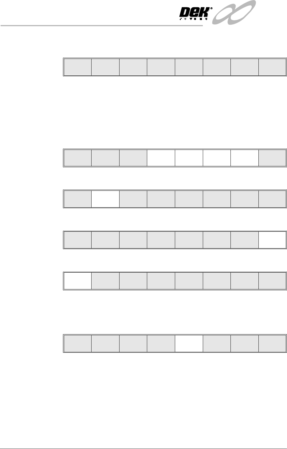
If the Camera Idle Position in Set Preferences is set to Behind Rail, the
following window and menu bar is displayed:
Selecting Continue Run clears the warning window and the print cycle
continues.
Selecting End Run clears the warning window, the print cycle is aborted and
control is returned to the ready page.
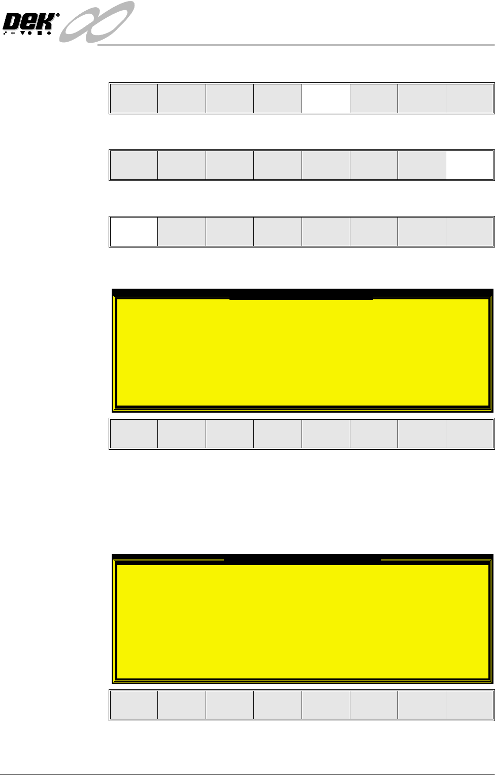
If the Unload Board Start in Set Preferences is set to Separation, the follow-
ing window and menu bar is displayed:
Selecting Continue Run clears the warning window and the print cycle
continues.
Mode
Load
Data
Edit
Data
Setup
Squeegee
Change
Screen
Change
Tooling
Change
Language
Exit
Mode
Load
Data
Edit
Data
Setup
Squeegee
Change
Screen
Change
Tooling
Change
Language
Exit
Run
Open
Cover
Paste
Load
Clean
Screen
Adjust Setup Monitor Maint.
Camera Behind Rail Warning
The CAMERA HOME POSITION is set to 'Behind
Rail'
Ensure that no tooling pins or other
obstructions are on the table behind the
rear rail, as these could cause damage to
the camera.
This option will only have an effect for
boards that are less than 250mm wide.
This option can be disabled from the set
preference page.
Continue
Run
End
Run
Unload Board Speedup Warning
The UNLOAD BOARD SPEEDUP option is set to
'Separation'
With this option enabled it should be noted
that there is only a minimal clearance
between the underside of the board and any
tooling being used, while the board is being
unloaded.
This option must not be used for boards that
are populated on the underside, as this
could damage the boards.
Continue
Run
End
Run