DEK INFINITY USER MANUAL.pdf.pdf - 第266页
INFINIT Y ',163(&7,21 ',163(&7,21 6(78 3 8.26 User Manual Software Versi on 7 NOTE The message ‘ Use the mou se in the stencil v iew windo w to position and size the site or e dit the parame ters ’…
INFINITY
',163(&7,21
',163(&7,216(783
Software Version 7 User Manual 8.25
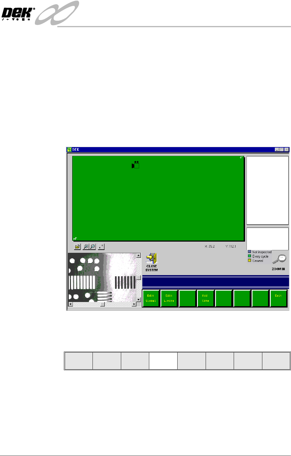
How to Add a Site The following procedure details a typical example of creating a new site with
the GUI board representation displaying the default standard board size format.
NOTE
It may be an advantage to have a board at hand in order to roughly estimate
required site locations.
1. Roughly position the camera to a desired site using either the mouse controls
or touchscreen (if available). Click on the desired area of the monitor board
representation.
2. A camera icon appears at the area selected. The machine camera moves to
the selected area (and board and stencil features are displayed in the vision
window). X and Y coordinates of the position is displayed.
3. To position the camera more accurately to the required inspection site, adjust
the X and Y screen bars displayed in the vision window.
4. Select Add Site.
The site name is automatically appended to a default name, ie SITE001.
If an existing site is selected the menu bar also includes Delete, Edit and
Inspect site function buttons.
NOTE
The operator can rename the new site as required by selecting Incr. or Decr.
and using the keyboard. Press Enter on completion.
Edit
Global
Edit
Limits
Add
Site
Exit
INFINIT
Y
',163(&7,21
',163(&7,216(783
8.26 User Manual Software Version 7
NOTE
The message ‘Use the mouse in the stencil view window to position and size
the site or edit the parameters’ is displayed in the message prompt bar.
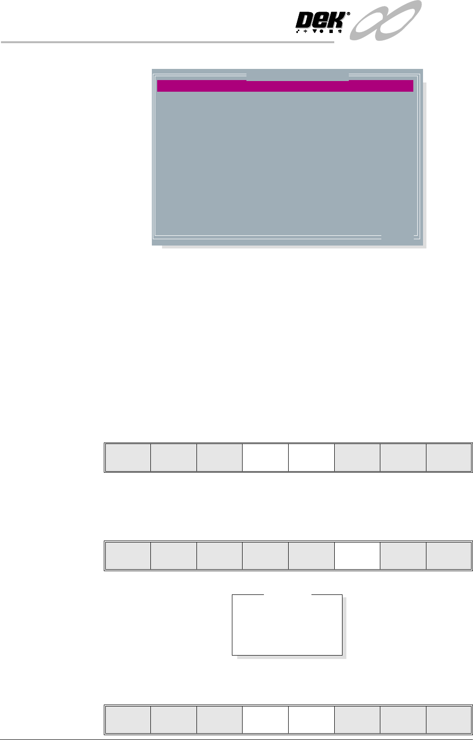
5. Adjust the following edit site parameters to suit the required application:
• Site Priority
• Stencil Inspect Type
• Board Inspect Type
• Site Alignment
• Site Limit ID
6. Highlight site limit ID using the Next and Previous keys.
NOTE
If new inspection file, only default limit is set.
7. Select Incr.
8. Using Next Limit or Previous Limit keys, highlight the limit set required
that was created in either add limits or edit limits.
SITE NAME
SITE PRIORITY
SITE BOARD TYPE
SITE STENCIL TYPE
SITE ALIGNMENT
SITE LIMIT ID
PASTE SCALING
SITE X COORD
SITE Y COORD
SITE WIDTH
SITE HEIGHT
SCREEN GRAPHIC X
SCREEN GRAPHIC Y
SITE1
EVERY CYCLE
ADVANCED
ADVANCED
X AND Y
DEFAULT
1.00
75.9
111.7
2.00
2.00
0.00
0.00
mm
mm
mm
mm
mm
mm
.. more
Edit Site Parameters
Learn
Screen
Light
Setup
Next Previous Incr. Decr. Exit
Learn
Screen
Light
Setup
Next Previous Incr. Decr. Exit
DEFAULT
COARSE
BGA
QFP
Limit Sets
Use
Limit
Next
Limit
Previous
Limit
Exit
INFINITY
',163(&7,21
',163(&7,216(783
Software Version 7 User Manual 8.27
9. Select Use Limit.
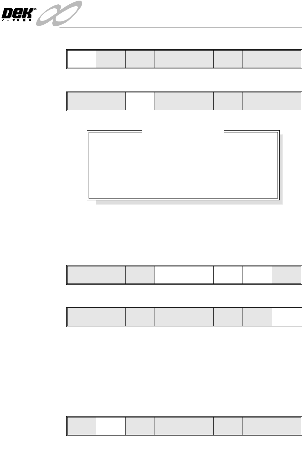
Lighting Setup 1. Select Light Setup.
Figure 8-8 Green Camera Lighting Parameters
2. Using the Next, Previous, Incr. and Decr. keys, adjust the lighting
parameters to a level whereby the stencil and board pads are just whiting out,
without blooming, default level 8 is usually adequate for the majority of
setups.
3. Select Exit.
Site Setup 4. Using one of the controls listed, carry out the following:
a. Mouse - Drag and drop the red Region Of Interest box (ROI) to the desired
position.
b. Touchscreen (if available) - Drag the red ROI box to the desired position.
c. Manual Function Buttons - Next, Previous, Incr. and Decr. keys adjust
the ROI position via the parameters.
5. Select Learn Screen.
The message ‘Stencil Learnt. Use the mouse in the board view to align
the board graphic or edit the parameters’ is displayed in the message
prompt bar.
Use
Limit
Next
Limit
Previous
Limit
Exit
Learn
Screen
Light
Setup
Next Previous Incr. Decr. Exit
8
8
8
8
-1.5
-1.5
3.0
3.0
mm
mm
mm
mm
Inspection Lighting Parameters
SCREEN VERTICAL
SCREEN OBLIQUE
BOARD VERTICAL
BOARD OBLIQUE
WINDOW LEFT
WINDOW TOP
WINDOW WIDTH
WINDOW HEIGHT
Next Previous Incr. Decr. Exit
Next Previous Incr. Decr. Exit
Add
Site
Learn
Screen
Light
Setup
Next Previous Incr. Decr. Exit