DEK INFINITY USER MANUAL.pdf.pdf - 第325页
INFINITY &21680$ %/(5( 3/(1,6+0(1 76 352)/2: Soft ware Ver sion 7 User Manual 9.41 5. If the ProFlow unit ’ s base cover is still fitted continue wit h Step 6. If the ProFlow unit ’ s base cover has been removed go …
INFINITY
&21680$%/(5(3/(1,6+0(176
352)/2:
9.40 User Manual Software Version 7
PROFLOW
Introduction This Section details the various procedures for the replenishment of the ProFlow
unit. A separate ‘Best Working Practices’ guide is also available, detailing
common procedures for the replenishment, housekeeping and maintenance of
ProFlow transfer heads (DEK Part No.171280). It is recommended that the Best
Working Practices guide is used in conjunction with any of the following
replenishment procedures.
NOTE
ProFlow Best Working Practices Manuals can be ordered online at
http://www.dek.com or email spares@dek.com quoting DEK Part No.171280.
ProFlow Cassette
Change
It is necessary at intervals to fit a new ProFlow cassette into the ProFlow transfer
head. If the cassette is empty at the end of a print stroke, the warning window
‘Print Medium Low. Please Replenish.’ is displayed.
WARNING
SOLDER PASTE AND SOLVENTS. WHEN USING OR HANDLING ANY SOLDER
PASTE OR SOLVENT FORMULATION THE MANUFACTURERS’ RECOMMEND
SAFETY PRECAUTIONS MUST BE STRICTLY ADHERED TO.
WARNING
PROTECTIVE CLOTHING. APPROVED PROTECTIVE CLOTHING SHOULD BE
WORN BY SOLDER PASTE AND SOLVENT HANDLERS AT ALL TIMES TO
ELIMINATE FUME INHALATION, EYE CONTACT, SKIN CONTACT AND
INGESTION.
NOTE
When using a ProFlow transfer head for the first time or if the transfer head
conditioning chamber has been cleaned, ie free from solder paste. The condi-
tioning chamber must be primed first with the print medium. Two ProFlow
cassettes are required, the first ProFlow cassette is used to prime the condition-
ing chamber. The second ProFlow cassette is fitted ready for machine opera-
tion.
The ProFlow cassette can be fitted or changed prior to and during a print run.
Prior to a Print Run The ProFlow cassette can be fitted or changed prior to selecting Run.
1. If ProFlow is in the home position continue from Step 2. If ProFlow is in the
contact position go to Step 19.
2. Select Setup (F6).
3. Select Setup ProFlow (F4).
4. Select Load Cassette (F4). The message ‘Has the ProFlow unit’s base
cover been removed?’ is displayed.
Run Head
Knead
Paste
Clean
Screen
Adjust Setup Monitor Maint.
Mode
Load
Data
Edit
Data
Setup
ProFlow
Change
Screen
Change
Tooling
Change
Language
Exit
Change
ProFlow
Load
Cassette
Prime
ProFlow
Exit
INFINITY
&21680$%/(5(3/(1,6+0(176
352)/2:
Software Version 7 User Manual 9.41
5. If the ProFlow unit’s base cover is still fitted continue with Step 6. If the
ProFlow unit’s base cover has been removed go to Step 12.
6. Select Remove Cover (F8). The message ‘Open the printer cover and
remove the ProFlow unit’s base cover’ is displayed.
7. Open the front printhead cover.
8. Remove the ProFlow unit’s base cover.
9. Close the front printhead cover.
10.Press the System button.
11. Select Exit (F8).
12.Select Yes (F1). The message ‘The ProFlow unit will be placed in the
REAR envelope’ is displayed.
13. If the ProFlow unit is required to be placed in another envelope continue with
Step 14. If the ProFlow unit is required to be placed in the machine preferred
envelope go to Step 18.
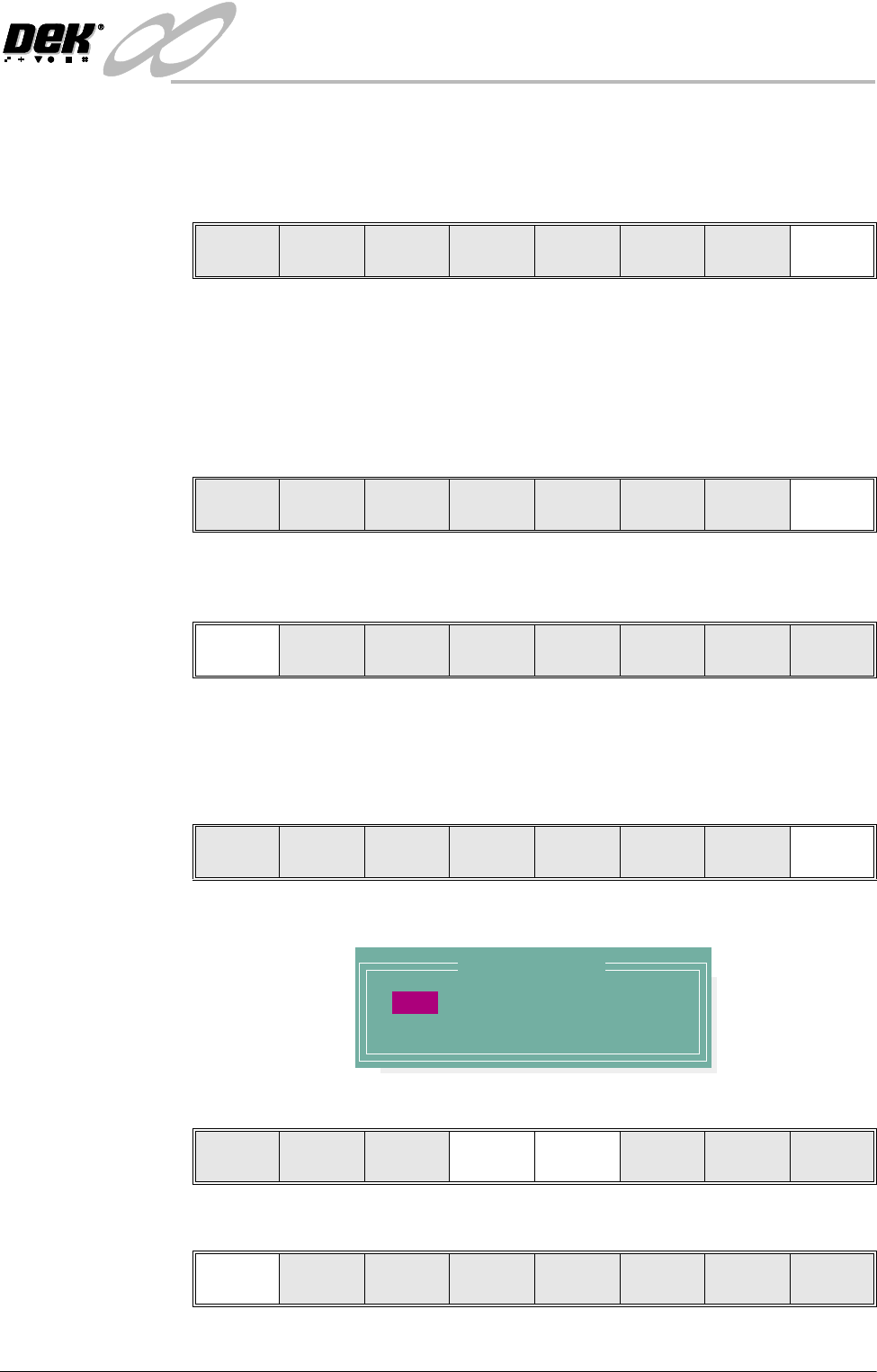
14.Select, Select Another (F8).
The following window is displayed:
15.Use the Next or Previous keys (F4 or F5) to highlight Front.
16.Select Use (F1).
Yes
Remove
Cover
Exit
Yes
Remove
Cover
Proceed
Select
Another
Preferred Envelope
REAR
FRONT
Use Next Previous Exit
Use Next Previous Exit
INFINITY
&21680$%/(5(3/(1,6+0(176
352)/2:
9.42 User Manual Software Version 7
17.Select Exit (F8).
18.Select Proceed (F1). The ProFlow unit is placed in contact with the stencil.
19.Open the front printhead cover.
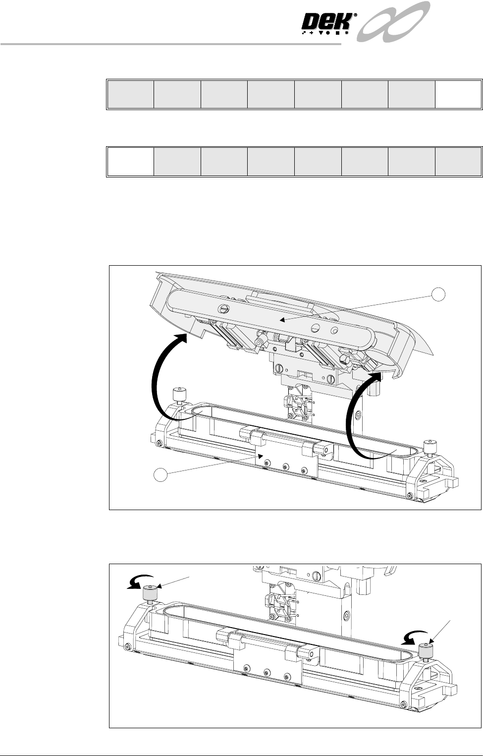
20.To gain access to the transfer head (1), release the latch on the front of the
pressure mechanism (2) and raise the mechanism forward and upwards to
engage the spring locking device.
21.To release the carrier from the transfer head, unscrew the thumbscrews at
each end of the carrier to loosen the clamp brackets.
Use Next Previous Exit
Proceed
Select
Another
2
1
Thumbscrew
Thumbscrew
Loosening Carrier Brackets