DEK INFINITY USER MANUAL.pdf.pdf - 第334页
INFINITY &21680$ %/(5(3/ (1,6+0(1 76 352)/2: 9.50 User Manual Software Versi on 7 10. Carefully remove the wipers by loosening the six screws securing each wiper retaining strip. Dispose of damaged wipers in accord …
INFINITY
&21680$%/(5(3/(1,6+0(176
352)/2:
Software Version 7 User Manual 9.49
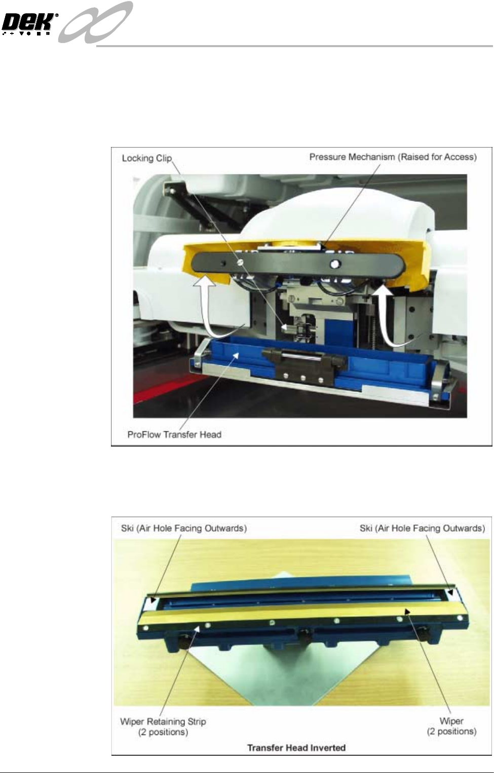
6. Release the latch on the front of the pressure mechanism and raise the
mechanism forwards and upwards to engage the spring locking device.
7. Open the locking clip securing the transfer head to the pressure mechanism
and carefully slide the transfer head out and away from the pressure mecha-
nism.
8. Invert the ProFlow transfer head and place onto the maintenance stand
(provided with the equipment).
9. Remove the cover from the ProFlow transfer head unit.
INFINITY
&21680$%/(5(3/(1,6+0(176
352)/2:
9.50 User Manual Software Version 7
10.Carefully remove the wipers by loosening the six screws securing each wiper
retaining strip. Dispose of damaged wipers in accordance with local
authority guide lines.
11. Carefully remove both skis. Dispose of damaged skis in accordance with
local authority guide lines.
12.Prior to fitting replacement items ensure the area around the wipers and skis
is free from print medium.
13.Fit replacement wipers into position ensuring both wipers are fully home
against the wiper securing screws.
NOTE
If fitting stepped etched wipers, ensure that the stepped edge of each wiper
is facing outwards (wiper example in figure below refers).
14.Fully tighten the wiper retaining strip screws.
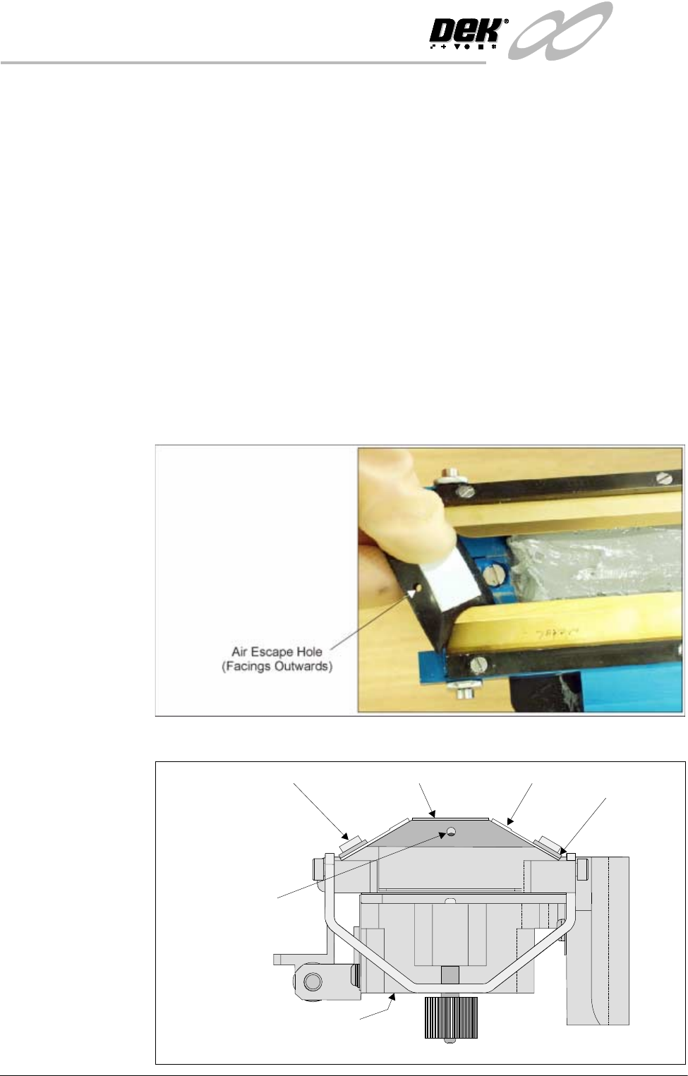
15.Slide each ski between the wipers until they are flush with the ends of the
wipers, (ensure the air escape hole on each ski faces outwards of the unit,
figure below refers.)
16.Fit the cover.
Ski
Ski Air Escape Hole
Wiper
ProFlow Transfer Head (Inverted)
Wiper
Retaining Strip
Inverted Transfer Head (End View)
Wiper Securing Screw
INFINITY
&21680$%/(5(3/(1,6+0(176
352)/2:
Software Version 7 User Manual 9.51
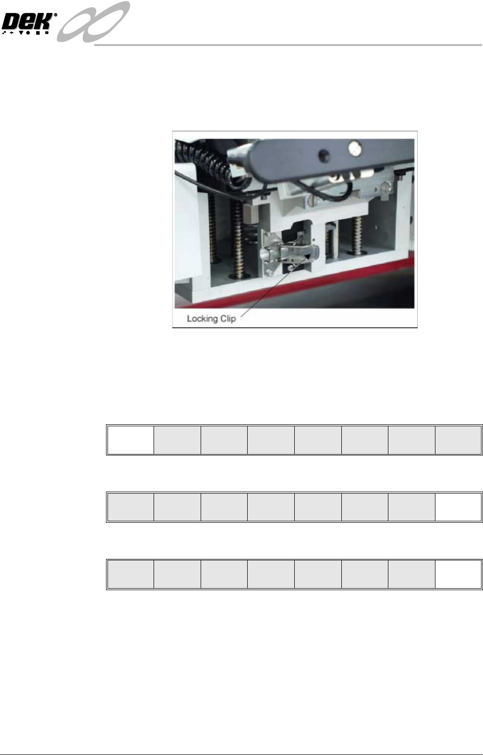
17.Check that the locking clip on the pressure mechanism is in the unlocked
position. Locate and fit the ProFlow transfer head unit to the pressure
mechanism by means of the two locating dowels. Slide the unit onto the
pressure mechanism. Once the unit is slid fully home, it is secured by closing
the locking clip.
18.Lower the pressure mechanism using the flush pull latch ensuring the
mechanism latch is engaged and is secured into place.
19.Close the front printhead cover.
20.Press the System button.
21.Press Continue (F1).
22.Press Exit (F8).
23.Press Exit (F8).
Continue
Change
ProFlow
Load
Cassette
Prime
ProFlow
Exit
Mode
Load
Data
Edit
Data
Setup
ProFlow
Change
Screen
Change
Tooling
Change
Language
Exit