DEK INFINITY USER MANUAL.pdf.pdf - 第335页
INFINITY &21680$ %/(5( 3/(1,6+0(1 76 352)/2: Soft ware Ver sion 7 User Manual 9.51 17. Check that the locking clip on the pressure mechanism is in the unlocked position. Locate and fit the ProFlow transfer head unit…
INFINITY
&21680$%/(5(3/(1,6+0(176
352)/2:
9.50 User Manual Software Version 7
10.Carefully remove the wipers by loosening the six screws securing each wiper
retaining strip. Dispose of damaged wipers in accordance with local
authority guide lines.
11. Carefully remove both skis. Dispose of damaged skis in accordance with
local authority guide lines.
12.Prior to fitting replacement items ensure the area around the wipers and skis
is free from print medium.
13.Fit replacement wipers into position ensuring both wipers are fully home
against the wiper securing screws.
NOTE
If fitting stepped etched wipers, ensure that the stepped edge of each wiper
is facing outwards (wiper example in figure below refers).
14.Fully tighten the wiper retaining strip screws.
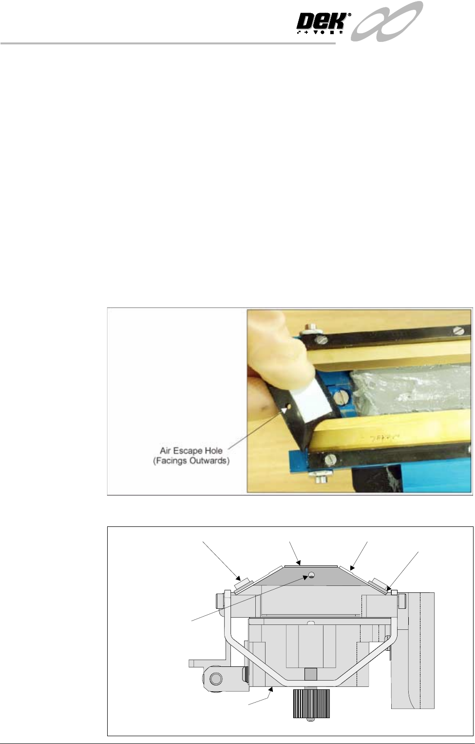
15.Slide each ski between the wipers until they are flush with the ends of the
wipers, (ensure the air escape hole on each ski faces outwards of the unit,
figure below refers.)
16.Fit the cover.
Ski
Ski Air Escape Hole
Wiper
ProFlow Transfer Head (Inverted)
Wiper
Retaining Strip
Inverted Transfer Head (End View)
Wiper Securing Screw
INFINITY
&21680$%/(5(3/(1,6+0(176
352)/2:
Software Version 7 User Manual 9.51
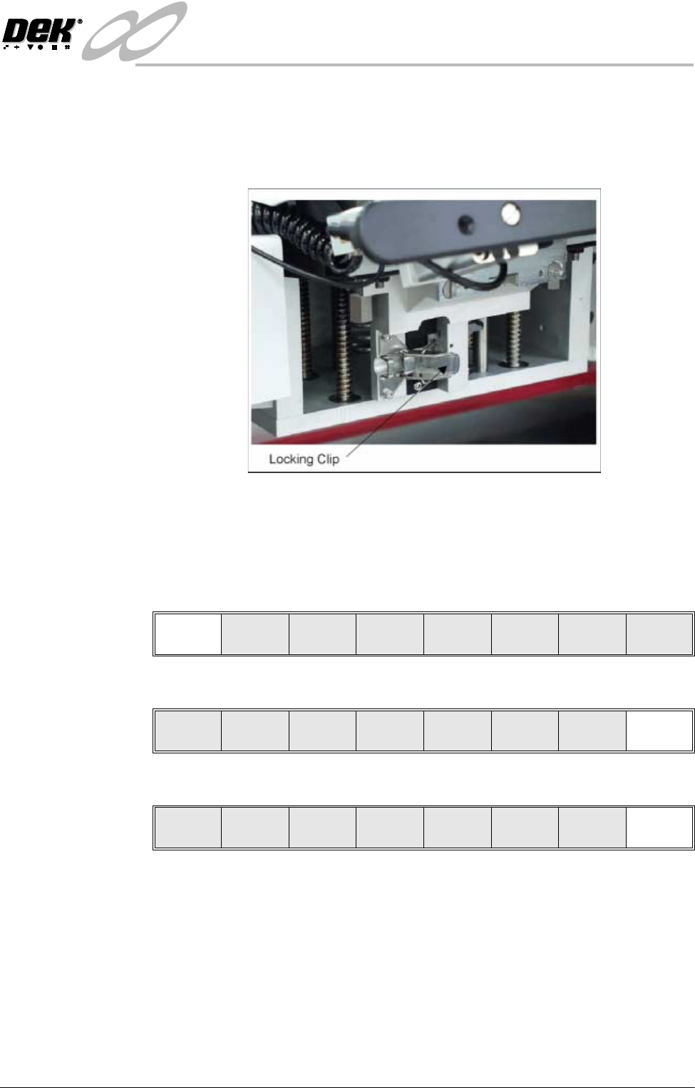
17.Check that the locking clip on the pressure mechanism is in the unlocked
position. Locate and fit the ProFlow transfer head unit to the pressure
mechanism by means of the two locating dowels. Slide the unit onto the
pressure mechanism. Once the unit is slid fully home, it is secured by closing
the locking clip.
18.Lower the pressure mechanism using the flush pull latch ensuring the
mechanism latch is engaged and is secured into place.
19.Close the front printhead cover.
20.Press the System button.
21.Press Continue (F1).
22.Press Exit (F8).
23.Press Exit (F8).
Continue
Change
ProFlow
Load
Cassette
Prime
ProFlow
Exit
Mode
Load
Data
Edit
Data
Setup
ProFlow
Change
Screen
Change
Tooling
Change
Language
Exit
INFINITY
&21680$%/(5(3/(1,6+0(176
352)/2:
9.52 User Manual Software Version 7
Rechargeable Transfer Heads
It is necessary at intervals to replenish the rechargeable transfer head. If there
is no print medium in the transfer head at the end of a print stroke, the warning
window ‘Print Medium Low. Please Replenish.’ is displayed.
WARNING
SOLDER PASTE AND SOLVENTS. WHEN USING OR HANDLING ANY SOLDER
PASTE OR SOLVENT FORMULATION THE MANUFACTURERS’ RECOMMEND
SAFETY PRECAUTIONS MUST BE STRICTLY ADHERED TO.
WARNING
PROTECTIVE CLOTHING. APPROVED PROTECTIVE CLOTHING SHOULD BE
WORN BY SOLDER PASTE AND SOLVENT HANDLERS AT ALL TIMES TO
ELIMINATE FUME INHALATION, EYE CONTACT, SKIN CONTACT AND
INGESTION.
Initial Fill If an empty/new rechargeable transfer head is to be used prior to printing. The
transfer head unit is to be initially charged in accordance with the following:
1. Ensure the empty transfer head is fitted with a base cover.
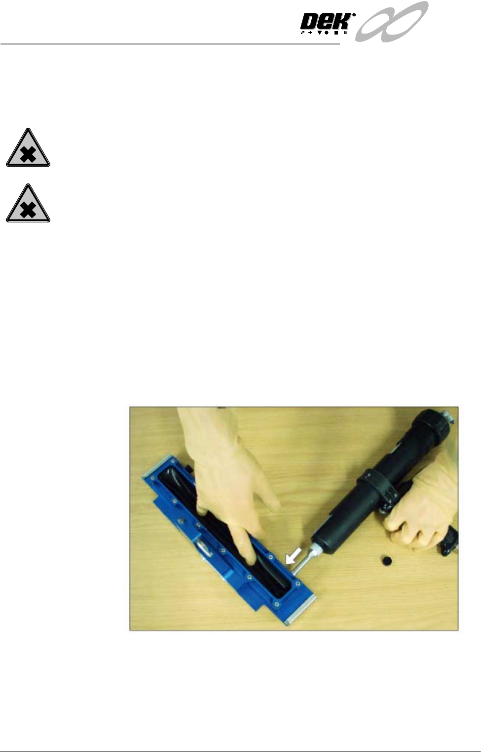
2. Using the recharging gun (mastic or pneumatic gun). Load a standard
cartridge and fit the long recharging nozzle to the cartridge.
NOTE
To prevent air bubbles, ensure that the long nozzle is charged with paste
prior to carrying out the next Step.
3. Starting at one end of the unit, remove the filling hole bayonet cap and insert
the recharging nozzle into the unit, (figure below refers).
4. Start filling the cavity, at the same time push the diaphragm down with
fingers (Step 3 Figure refers), to feel the paste filling the void. Whilst the
paste is filling, gently knead the diaphragm to evenly distribute the paste and
also prevent ballooning. Fill approximately one third the length of the unit.
On completion remove the nozzle and refit the bayonet cap.